Advantix base unit for Advantix shower channel
Product information
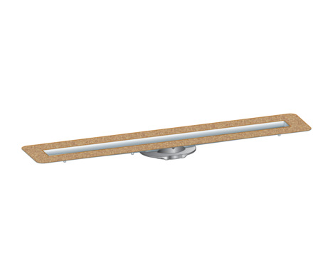
Advantix base unit for Advantix shower channel
for bonded sealing (tiled shower) with sealing mat
| Year built (from): | 01-04-2016 |
Trade mark rights exist for this document; for further information, go to viega.com/legal .
Target groups
The information in this instruction manual is directed at the following groups of people:
Heating and plumbing experts and trained personnel
Consumers
Individuals without the abovementioned training or qualification are not permitted to mount, install and, if required, maintain this product. This restriction does not extend to possible operating instructions.
The installation of Viega products must take place in accordance with the general rules of engineering and the Viega instructions for use.
Labelling of notes
Warning and advisory texts are set aside from the remainder of the text and are labelled with the relevant pictographs.

DANGER!
This symbol warns of possible life-threatening injury.

WARNING!
This symbol warns of possible serious injury.

CAUTION!
This symbol warns of possible injury.

NOTICE!
This symbol warns of possible damage to property.

INFO!
This symbol gives additional information and hints.
About this translated version
This instruction for use contains important information about the choice of product or system, assembly and commissioning as well as intended use and, if required, maintenance measures. The information about the products, their properties and application technology are based on the current standards in Europe (e.g. EN) and/or in Germany (e.g. DIN/DVGW).
Some passages in the text may refer to technical codes in Europe/Germany. These should serve as recommendations in the absence of corresponding national regulations. The relevant national laws, standards, regulations, directives and other technical provisions take priority over the German/European directives specified in this manual: The information herein is not binding for other countries and regions; as said above, they should be understood as a recommendation.
Standards and regulations
The following standards and regulations apply to Germany / Europe and are provided as a support feature.
Regulations from section: Sealing
Scope / Notice | Regulations applicable in Germany |
|---|---|
Stress class of the underground, as well as suitable bonded sealing | ZDB-Merkblatt 8/2012 |
Stress class of the underground, as well as suitable bonded sealing | Leitfaden zur Abdichtung im Verbund (AIV) |
Approved bonded sealings with proof of practicability in keeping with building law for stress classes A and AO | ETAG 022 T1 |
Approved bonded sealings with proof of practicability in keeping with building law for stress classes A, B and C | DIBt-Bauregelliste A, Teil 2 des DIBt und Prüfgrundsätze für Abdichtungen im Verbund (PG AIV-F) |
Permitted bonded sealings | EN 14891 |
Sealing of inside rooms | DIN18534 |
Regulations from section: Media
Scope / Notice | Regulations applicable in Germany |
|---|---|
Typical domestic wastewater | DIN 1986‑3 |
Regulations from section: Sound protection
Scope / Notice | Regulations applicable in Germany |
|---|---|
Fulfilled noise protection requirements | DIN 4109 |
Fulfilled noise protection requirements | VDI 4100 |
Regulations from section: Important notes
Scope / Notice | Regulations applicable in Germany |
|---|---|
Dimensions of slots and recesses | EN 1996 |
Certification
Data acc. to DIN EN 1253, Table 7
Manufacturer | Viega GmbH & Co.KG |
Manufacturer identification mark |  |
Certificate of conformity |  |
Address | Viega GmbH & Co.KG |
Relevant standard | DIN EN 1253‑1 |
Load class | K3 |
Product class with respect to temperature behaviour | A |
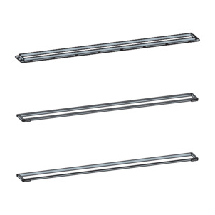
Product description
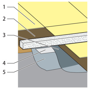
Overview
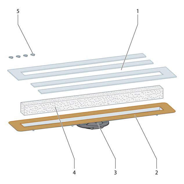
- 1 - Building protection cardboard
- 2 - Base unit
- 3 - Connection element
- 4 - Hard foam block
- 5 - Adhesive points
The following parts are not included in the scope of delivery and must be ordered separately:
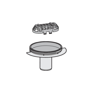
Odour trap
Adjustable feet
Mounting frame
Grate
Sealing material
Technical data
Material |
|---|
Drainage capacity |
Dimensions |
Installation height |
Water seal level |
Load class |
Stainless steel 1.4301 |
with odour trap model 4982.92: 95–160 mm with odour trap model 4982.93: 70–95 mm with odour trap model 4982.94: 40 mm and up without odour trap model 4982.83: 40 mm and up |
with odour trap model 4982.92 and 4982.94: 50 mm with odour trap model 4982.93: 25 mm |
K = 300 kg |
Sound protection
The measured sound level during water drainage is 19 dB(A). For information on sound protection requirements met, see Regulations from section: Sound protection .
Information for use
Sealing
Bonded sealing
To protect against moisture penetration, apply sealing foils, which are to be processed in liquid state, directly below the tiles on screed and walls. The determination of the stress class and the underground as well as the selection of the suitable bonded sealing must be carried out in compliance with the valid standards and regulations, see: Regulations from section: Sealing .
Important note
Careful planning is required for sealing. In addition, depending on the individual dampness wear class and the type of foundation, a suitable thin bed bonded sealing with a building regulations certificate of suitability must be chosen.
Furthermore, the following factors should be taken into account:
The drain or shower channel must be equipped with a special flange, which has an adhesive surface and a width of at least 50 mm.
For bridging the material change from drain to screed, either a suitable sealing collar or sealing tape designed for overlapping with the thin bed bonded sealing over a width of at least 50 mm must be used.
The screed must be laid at a minimum incline of 1–2%.
The installation must be carried out in acc. with the mounting instructions and the manufacturer's information.
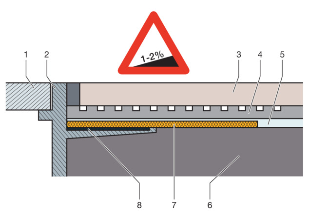
- 1 Grate
- 2 Top piece with adhesive flange
- 3 Tile
- 4 Tile cement
- 5 Bonded sealing
- 6 Screed
- 7 Sealing collar
- 8 Adhesive
Permitted bonded seals
In connection with suitable drains, only approved bonded sealings with proof of practicability in keeping with building law may be used. See Regulations from section: Sealing .
Information regarding the procedure can be found in the instructions for use of the corresponding product.
Fire protection
Advantix shower channels and drains can both be fitted to be fire proof. The R120 pipe lead-in can be used for this purpose in the floor construction. In this way, a fire resistance time of up to 120 minutes can be achieved.
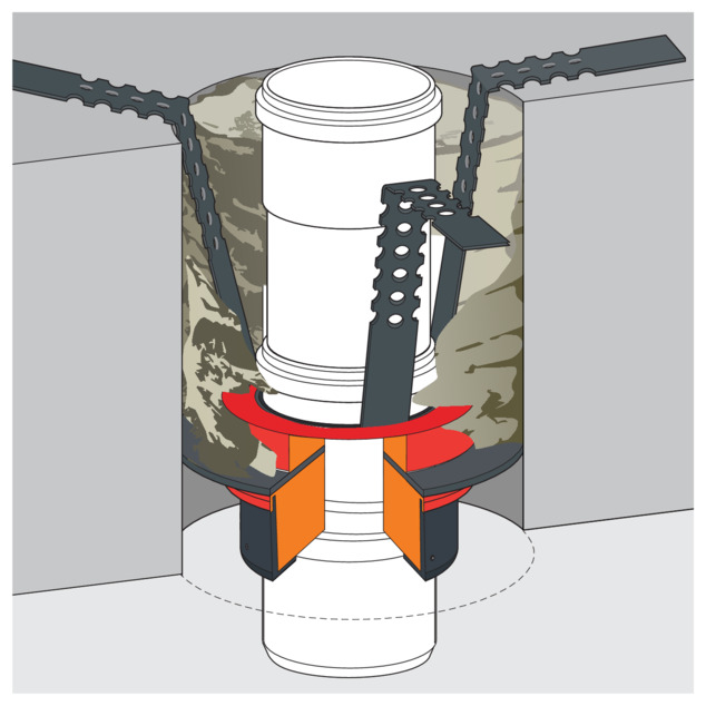
For mounting instructions for the R120 pipe lead-in see model 4923.5, art. no. 491 673.
Required accessories
The following parts are not included in the scope of delivery and can be ordered separately:
Odour trap
Adjustable feet
Mounting frame
Shower channel drain
Grate (see catalogue)
Sealing tape for Advantix shower channels, model 4964.95, art. no. 619 121
If required: mounting adhesive, model4938.22, art. no. 571 788
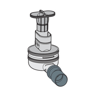
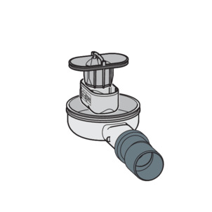
Odour trap
Model |
|---|
Water seal level |
Construction height |
Drainage capacity |
4982.92 |
50 mm |
95–155 mm |
Accumulation height 10 mm: 0.5 l/s Accumulation height 20 mm: 0.55 l/s |
Model |
|---|
Water seal level |
Construction height |
Drainage capacity |
4982.93 |
25 mm |
70–110 mm |
Accumulation height 10 mm: 0.4 l/s Accumulation height 20 mm: 0.45 l/s |
Model |
|---|
Water seal level |
Construction height |
Drainage capacity |
4982.94 |
50 mm |
95 mm and up |
Accumulation height 10 mm: 0.9 l/s Accumulation height 20 mm: 1.1 l/s |
Shower channel drain
Model |
|---|
Construction height |
Drainage capacity |
4982.83 |
95 mm and up |
Accumulation height 10 mm: 1.3 l/s Accumulation height 20 mm: 1.2 l/s |
Adjusting feet set
For installation height 95–155 mm
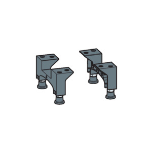
For installation height 70–110 mm
Mounting frame
Rectangular design
Round design
Standard version
Handling
Assembly information
Important note
Before assembly:
Check if the drainage capacity of the model chosen is sufficient for the arising water volume Drainage capacity .
An adequate level of floor covering stability must be guaranteed Technical data . This can be achieved either through an adequate screed thickness or another alternative solution. Relevant measures must be considered before mounting.
The dimensions of slots and recesses must be in compliance with the regulations from section Regulations from section: Important notes .
During assembly:
Observe installation dimensions.
Do not use mounting adhesive older than 18 months.
Position the shower channel in such a way that the grate is removable.
After assembly:
The shower channel must be fully lined with mortar.
Coordinate all relevant installation details, especially regarding the bonded sealing, with those responsible for the subsequent work.
Installation dimensions
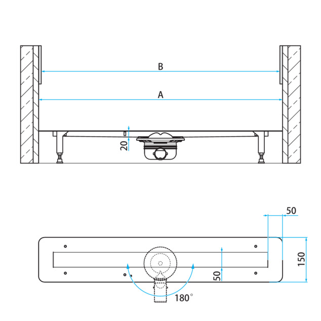
Art. no. | A1) | B2) | Standard dimension |
|---|---|---|---|
736 965 | 770 | 670 | 750 |
736 972 | 820 | 720 | 800 |
736 989 | 920 | 820 | 900 |
736 996 | 1020 | 920 | 1000 |
737 009 | 1220 | 1120 | 1200 |
| 1) | linear dimension of the base unit |
| 2) | inner dimension of the base unit (grate size) |
Tools and materials
Special tools
Fork spanner size 8 for grate mounting
Drill, 6 mm
Tool for the removal of the grate (e.g. model 4965.90, art. no. 689 704)
Assembly
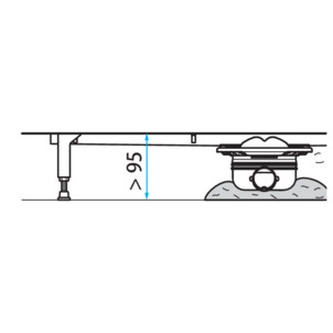
Determine height
Depending on the selected odour trap, different installation heights can be implemented.
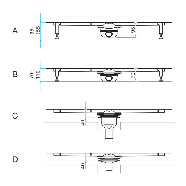
- A - Model 4982.92
- B - Model 4982.93
- C - Model 4982.94
- D - Model 4982.83
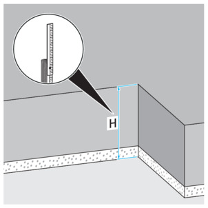
-
Determine installation height (H).
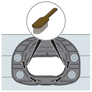
-
Check the connection element for soiling, clean if necessary.
Mounting base unit
Mounting the drain
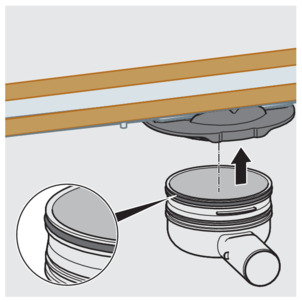
-
Insert the greased sealing element into the casing.
Observe the sealing element is correctly in place (see arrow).
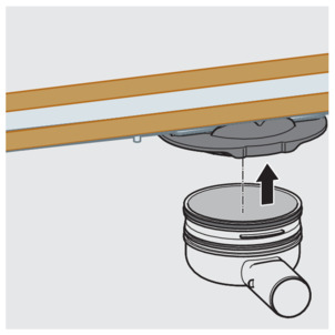
-
Press the drain straight into the connection element until it snaps home.
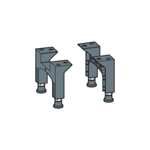
Mounting the adjusting feet and drain sockets
-
For installation heights of up to 70 mm:
Align the base unit in the mortar bed.
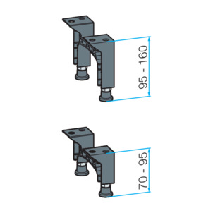
-
Select the adjusting feet set in accordance with the installation height:
A – Model 4982.90, installation height: 95–160 mm
B – Model 4982.91, installation height: 70–95 mm
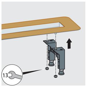
-
Mount the adjusting feet.
Regarding mounting, refer to the instructions for use for the adjusting feet set.
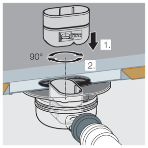
-
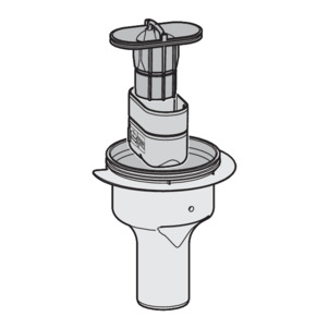
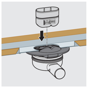
Put in the odour trap insert.
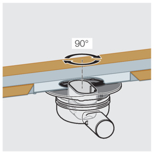
-
Turn the odour trap insert clockwise through 90°.
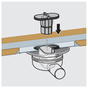
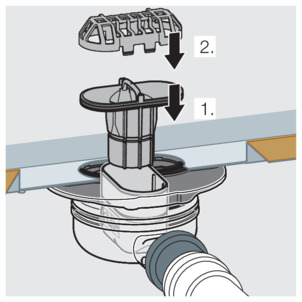
-
Insert the immersion pipe of the odour trap.
-
Inserting the immersion pipe of the odour trap fastens the odour trap insert.
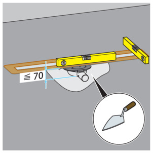
Aligning shower channel
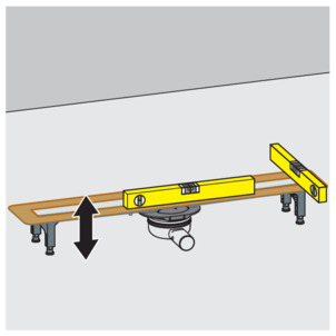
-
Adapt the base unit to screed height by adjusting the feet.
-
Align the base unit horizontally in all directions.
-
With an installation height above 95 mm, provide the odour trap with mortar bedding to prevent slippage.
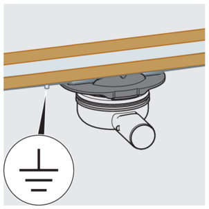
-
Check whether grounding is required.
Connecting shower channel
The connection to the wastewater system must be completed before the drain can be installed in the floor construction.
Requirements:
A pipe to the planned drainage position is already in place for the connection to the wastewater system.
The drainpipe has an internal profile seal.
Proceed as follows:
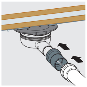
-
Insert the drain socket into the drainpipe as far as it will go.
Preparing for further work
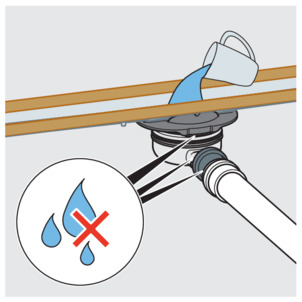
-
Fill the shower channel with water.
-
Check the drain casing and pipeline for leak tightness.
Lining with screed
NOTICE!
Product damage due to improper installation
If cavities form during the lining of the shower channel, leaks may occur when pressure is applied.
Inform the subsequent workers that the shower channel must be fully lined and that there must be no cavities generated.
-
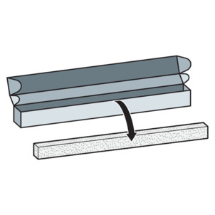
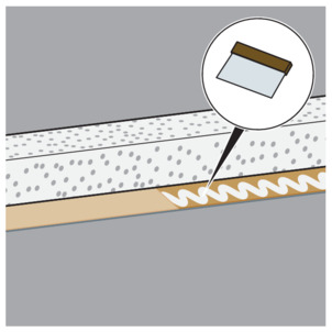
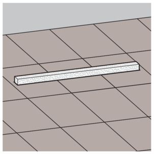
Remove the hard foam block from the packaging.
-
Insert the protective insert made of hard foam.
The protective insert acts as a mounting aid and protection against contamination.
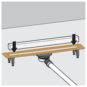
-
Mount the site protection.
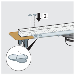
-
Stick on the adhesive points and remove the protective cover.
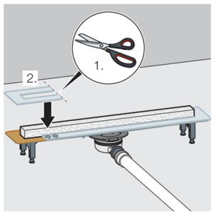
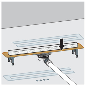
-
Shorten the second part of the site protection if applicable, and mount it.
Screed and floor tiles must be laid at an incline of 1–2 % in the direction of the shower channel.
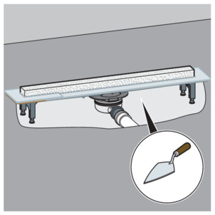
-
Line the shower channel fully with screed up to the upper edge of the flange.
Sealing the shower channel
Requirements
The flange must be clean and free from material residue. If necessary, clean the flange.
INFO!
The sealing tape is not included with delivery. Viega recommends model 4964.95, art. no. 619 121.
Sealing can take place with or without the use of mounting adhesive. The mounting adhesive is not included in the scope of delivery. Viega recommends model 4938.33, art. no. 571 788.
Sealing with bonded sealing, without mounting adhesive
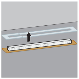
-
Remove the site protection.
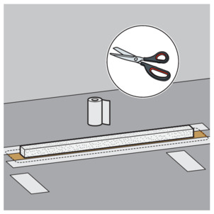
-
Cut the sealing tape generously. The strips must overlap when stuck on.
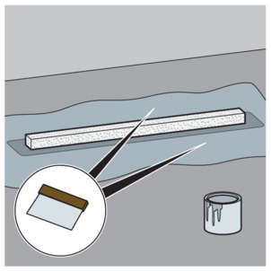
-
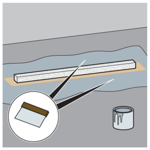
Apply the first layer of bonded sealing generously onto the screed and the flange.
Observe the instructions for use of the manufacturer of the bonded sealing.
-
Place the sealing tape on the flange in such a way that flange and screed are evenly covered.
-
Press the sealing tape firmly into the bonded sealing. Overlap the corners in the process.
-
Stick the overlapping tape strips together at the corners with bonded sealing.
-
Thoroughly work over the adhesive surfaces with a roller.
-
Apply the second layer of bonded sealing generously on the sealing tape and screed.
-
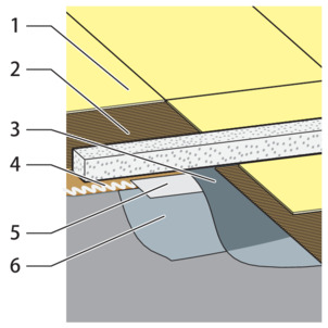
Layer build-up sealing:
1 – Tiles
2 - Tile adhesive
3 – Bonded sealing (2)
4 - Sealing tape
5 – Bonded sealing (1)
If no cover trim is to be fitted, the floor can now be tiled Lay tiles (mounting without cover trim) .
Sealing with bonded sealing and mounting adhesive
-
Remove the site protection.
-
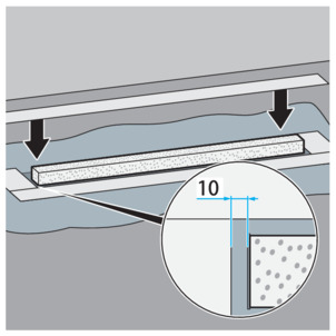
Cut the sealing tape to length so that the tape overlaps the flange and the screed.
Ensure that they overlap by at least 50 mm!
The sealing tape must enclose the entire shower channel.
-
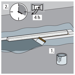
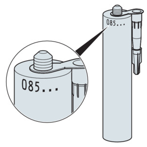
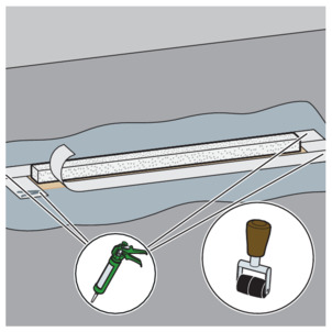
Use a suitable tool to open the cartridge of the mounting adhesive.
INFO!Check the expiry date on the cartridge.
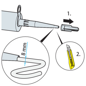
-
Unscrew the cartridge and cut it so that you can apply the adhesive in a strip of approx. 8 mm width.
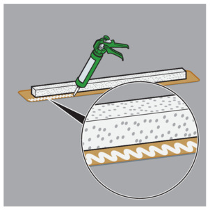
-
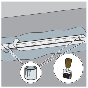
Apply the mounting adhesive to the flange.
-
Use a palette-knife to spread the mounting adhesive evenly.
-
Apply the first layer of bonded sealing generously onto the screed.
Observe the instructions for use of the manufacturer of the bonded sealing.
-
Place the sealing tape on the flange in such a way that flange and screed are evenly covered.
-
Press the sealing tape firmly onto the mounting adhesive and the bonded sealing. Overlap the corners in the process.
-
Stick the overlapping strips together at the corners with mounting adhesive.
-
Thoroughly work over the adhesive surface with a roller.
-
Apply the second layer of bonded sealing generously on the sealing tape and screed.
-
Layer build-up sealing:
1 – Tiles
2 - Tile adhesive
3 – Bonded sealing (2)
4 – Mounting adhesive
5 - Sealing tape
6 – Bonded sealing (1)
If no cover trim is to be fitted, the floor can now be tiled Lay tiles (mounting without cover trim) .
Mounting with Viega mounting frames
-
Regarding mounting, refer to the instructions for use for the mounting frame.
Model 4982.30
Model 4982.40
Model 4982.45
Installation with covering
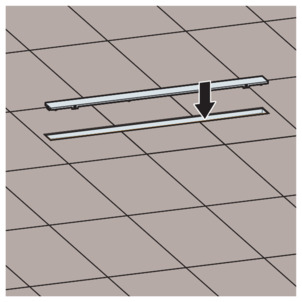
-
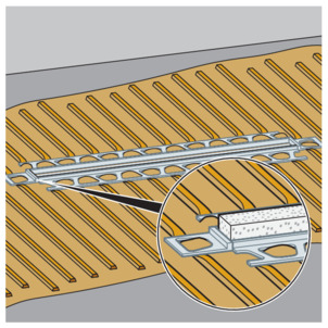
Glue the rail in a straight line at the protective insert.
-
Deburr the cutting edges.
-
Avoid differences in height between different parts of the rails.
-
The shower channel is now installed.
The floor can now be tiled Lay tiles (mounting without cover trim) .
Lay tiles (mounting without cover trim)
-
Lay the tiles right up to the edge of the protective insert.
Avoid sharp edges in the following places in the barefoot area:
on tiles
at surface ends
on mounting profiles
-
Polish the tile edge.
Finally, a grate must be mounted. See catalogue for suitable grates.
Regarding mounting, refer to the instructions for use of the grate.
Care
Care tips
Normal soap or a mild cleaning agent can be used for regular maintenance and prevention of lime scale on the grate and frame. Use no scouring agent or abrasive objects.
Strong stains, even around the drain unit and the odour trap, can be removed using typical household cleaner. Rinse the detergent very thoroughly with clear water after the prescribed dwell time. There should be no residue on the components.
Cleaning
Viega recommends using a mild cleaning agent, a cloth and a washing-up brush for cleaning.
Cleaning the drain
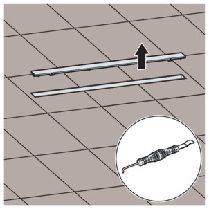
-
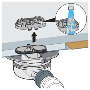
Remove the grate, for example with the removal tool model 4965.90, art. no. 689 704.
-
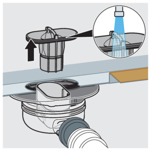
Remove the sieve and clean it under running water.
-
Remove the immersion pipe of the odour trap.
-
Clean the sieve and immersion pipe.
-
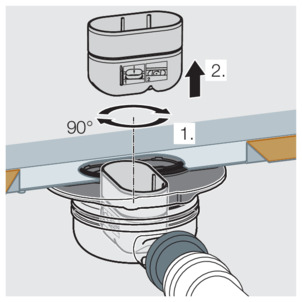
Remove the odour trap insert.
-
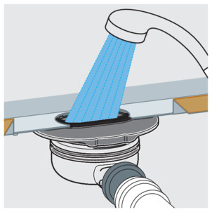
Clean the base unit.
-
Replace the odour trap insert.
-
Replace the immersion pipe.
-
Replace the sieve.
-
Replace the grate.
Clean shower channel
-
Remove the grate, for example with the removal tool model 4965.90, art. no. 689 704.
-
Clean the grate and shower channel.
-
Rinse with clean water.
-
Replace the grate in the shower channel.
Disposal
Separate the product and packaging materials (e. g. paper, metal, plastic or non-ferrous metals) and dispose of in accordance with valid national legal requirements.