Viega Eco Plus urinal element siphon sensor technology
Product information
Viega Eco Plus urinal element siphon sensor technology
for urinal with siphon sensor technology
| Year built (from): | 1.6.2015 |
Trade mark rights exist for this document, further information can be found at viega.com/legal .
Target groups
The information in this instruction manual is directed at the following groups of people:
Heating and sanitary professionals and trained personnel
SHK-FachkräfteTrained electricians
ElektrofachkräfteDrywall builder
It is not permitted for individuals without the abovementioned training or qualification to mount, install and, if required, maintain this product. This restriction does not extend to possible operating instructions.
The installation of Viega products must take place in accordance with the general rules of engineering and the Viega instructions for use.
Labelling of notes
Warning and advisory texts are set aside from the remainder of the text and are labelled with the relevant pictographs.

DANGER!
This symbol warns against possible life-threatening injury.
WARNING!
This symbol warns against possible serious injury.

CAUTION!
This symbol warns against possible injury.

NOTICE!
This symbol warns against possible damage to property.

INFO!
Notes give you additional helpful tips.
About this translated version
This instruction for use contains important information about the choice of product or system, assembly and commissioning as well as intended use and, if required, maintenance measures. The information about the products, their properties and application technology are based on the current standards in Europe (e. g. EN) and/or in Germany (e. g. DIN/DVGW).
Some passages in the text may refer to technical codes in Europe/Germany. These should serve as recommendations in the absence of corresponding national regulations. The relevant national laws, standards, regulations, directives and other technical provisions take priority over the German/European directives specified in this manual: The information herein is not binding for other countries and regions; as said above, they should be understood as a recommendation.
Standards and regulations
The following standards and regulations apply to Germany / Europe. National regulations can be found on the relevant web site of your country at viega.com/standards .
Regulations from section: Fields of application / Mounting conditions
Scope / Notice | Regulations applicable in Germany |
|---|---|
suitable masonry walls | EN 1996‑1‑1 |
suitable support profiles | DIN 18183 |
Regulations from section: Sound protection
Scope / Notice | Regulations applicable in Germany |
|---|---|
Fulfilled noise protection requirements | DIN 4109 |
Fulfilled noise protection requirements | DIN 4109 (additional sheet 2) |
Fulfilled noise protection requirements | VDI 4100 SSt I-SSt II |
Product description
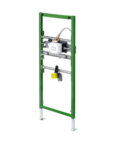
Overview

- 1 - urinal installation set
- 2 - threaded bolts for fixing sanitary objects
- 3 - adjustable feet
- 4 - drain elbow
- 5 - mounting bracket for drain elbow
- 6 - Viega Eco Plus element (8152.4)
- 7 - wall plate Rp ½
- 8 - double nipple R ½
- 9 - fixing set, model 8173*
- * not included in scope of delivery
Compatible components
The urinal element is compatible with the equipment set "Siphon sensor technology" model 8352.2.
It is suitable for all ceramics with a horizontal connection.
Sound protection
The urinal element complies with the noise insulation requirements specified in section Regulations from section: Sound protection .
Technical data
The product has the following technical data:
drain elbow |
|---|
Fitting connection |
Hole diameter for fixing in wooden frame construction |
Maximum height of urinal inlet from upper edge of the finished floor |
DN 50 |
Rp ½ |
11 mm |
880 mm |
Accessories
Required accessories

The fixing set model 8173 is required to secure.
Handling
Assembly information
Mounting conditions
Construction height
With the construction height, the marked height of the upper edge of the finished floor must be observed.
Actuation
The urinal element can be extended with the equipment set "Siphon sensor technology", model 8352.2.
Installation dimensions
Urinal element

Required tools
drill with 10 mm drill bit
ratchet with sockets: 13 mm / 17 mm
fork or ring spanner: 13 mm / 17 mm / 22 mm
Assembly
Mounting the urinal element
DANGER!
Danger due to electrical current
An electric shock can lead to burns and serious injury and even death.
Work on the electrics may only be carried out by trained electricians.
Always de-energise the connection line before work is commenced.
Masonry wall
INFO!
Masonry and concreted walls
You should use a support bracket (model 8165) when mounting multiple urinal elements with an interval of > 490 mm. Observe the instructions for use of the support bracket when mounting.

-
Determine and mark fixing points.
X1: 390 mm (model 8180.73)
X2: 440 mm (model 8173)
X3: 1100 mm

-
Drill holes.
-
Mount the fixing set with the fork spanner (size 13).

-
Align the height of the urinal element in accordance with the cutting check.
Determine construction height in accordance with the on-site marking of the upper edge of the finished floor.
x = Observe the instructions of the urinal manufacturer.
INFO!The construction height must be determined and adhered to exactly.
There are only limited possibilities available to remedy errors made during this assembly step, Construction height .

-
Set the installation depth of the pre-wall element with the fork spanner (size 17).

-
Attach urinal element to the floor using the fork spanner (size 13) and the screws and dowels supplied.

-
Mount drain elbow in mounting bracket.
-
Secure with a bracket.
-
Set height of the drain elbow (50 mm)

-
Mount threaded bolts.

-
Seal double nipple from one side.
-
Screw double nipple into the wall plate.

-
Secure water inlet onto the double nipple.

-
Seal supply fitting.
-
Screw supply fitting into the wall plate.

-
DANGER!
Risk of electric shock. Work on the electrics may only be carried out by trained electricians.
Lay the electrical cable in the installation set.
-
Connect water line.

-
Double-clad urinal element (2 x 12.5 mm).
Mounting in Viega Eco Plus
The urinal element can be installed in support profiles of 50 mm and 75 mm.
-
Determine the fixing points.
-
Align element.
-
Mount drain elbow, double nipple and water inlet.

-
If necessary, adjust the pre-mounted feet from 75 mm to 50 mm:
Pull the foot out and turn by 90°.

-
Attach urinal element to the floor using the fork spanner (size 13) and the screws and dowels supplied.

-
Determine construction height in accordance with the on-site marking of the upper edge of the finished floor.
-
Pull urinal element up (cutting check) and align.
x = Observe the instructions of the urinal manufacturer.
INFO!The construction height must be determined and adhered to exactly.
There are only limited possibilities available to remedy errors made during this assembly step, Construction height .

-
Screw the urinal element together laterally with the support profiles.

-
Connect water line.
-
DANGER!
Risk of electric shock. Work on the electrics may only be carried out by trained electricians.
Lay the electrical cable in the installation set.

-
Double-clad urinal element (2 x 12.5 mm).
Mounting in Viega Steptec

-
Align urinal module.
INFO!Observe the ceramic manufacturer's information when aligning the connections.
-
If necessary, swap the installation set with the mounting bracket and the crossbeam of the threaded bolts with each other.
-
Mount drain elbow, double nipple and water inlet.

-
Secure the module onto the open side of the Steptec rail with the slot nuts supplied.
-
Press the slot nut in gently and secure in the open rail side with a 90° turn.
-
If necessary, align the height of the urinal element.
-
Tighten slot nut with a fork spanner (size 17).
-
Connect water line.
-
DANGER!
Risk of electric shock. Work on the electrics may only be carried out by trained electricians.
Lay the electrical cable in the installation set.

-
Clad urinal element (1 x 12.5 mm).
Afterwards, install the sensor technology and the urinal. You will find information regarding the procedure in the instructions for use of the equipment set model 8352.2 and of the urinal.
Disposal
Separate the product and packaging materials (e. g. paper, metal, plastic or non-ferrous metals) and dispose of in accordance with valid national legal requirements.