Viega Eco Plus WC corner element
Product information
Viega Eco Plus WC corner element
Viega Eco Plus
| Year built (from): | 1.7.2007 |
Trade mark rights exist for this document, further information can be found at www.viega.com/legal-notices.
Target groups
The information in this instruction manual is directed at the following groups of people:
Heating and sanitary professionals and trained personnel
HVAC professionals
It is not permitted for individuals without the abovementioned training or qualification to mount, install and, if required, service this product. This restriction does not extend to possible operating instructions.
The installation of Viega products must take place in accordance with the general rules of engineering and the Viega instructions for use.
Labelling of notes
Warning and advisory texts are set aside from the remainder of the text and are labelled with the relevant pictographs.

DANGER!
This symbol warns against possible life-threatening injury.

WARNING!
This symbol warns against possible serious injury.

CAUTION!
This symbol warns against possible injury.

NOTICE!
This symbol warns against possible damage to property.

INFO!
Notes give you additional helpful tips.
About this translated version
This instruction for use contains important information about the choice of product or system, assembly and commissioning as well as intended use and, if required, maintenance measures. The information about the products, their properties and application technology are based on the current standards in Europe (e. g. EN) and/or in Germany (e. g. DIN/DVGW).
Some passages in the text may refer to technical codes in Europe/Germany. These should serve as recommendations in the absence of corresponding national regulations. The pertinent national laws, standards, regulations and guidelines, as well as other technical guidelines, have priority over German/European guidelines in this manual: The information is not binding for other countries and territories and should, as mentioned, be considered as support.
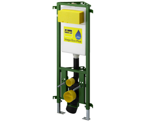
Product description
Overview
The WC element is equipped as follows:

- 1 - Viega Eco Plus WC element
- 2 - threaded rods for fixing sanitary objects (gauges for bore hole 180 or 230 mm)
- 3 - adjustable feet
- 4 - drain elbow
- 5 - 3 fixing heights for the WC ceramic: 330 mm / 350 mm / 370 mm
- 6 - Viega concealed cistern 2C
- 7 - marking 1.0 m above the upper edge of the finished floor
- 8 - fixing set (not included in the scope of delivery model 8173)
- 9 - site protection flush actuation
Compatible components
The element is compatible with all common sink basins.
The WC element is compatible with all common WC ceramics, even with larger projection (barrier-free).
The WC element can be extended by the following compatible components:
fixing set (model 8173)
connection installation set (model 8350.14)
Mount the components in accordance with the instructions for use of the components.
Connection installation set
The installation set is suitable for the connection of an electrical actuator. The installation set consists of an empty pipe, a hollow wall socket and the relative, required clip. The empty pipe connects the hollow wall socket with the concealed cistern.
Compatible flush plates
Product |
|---|
Standard |
Visign for Style |
Visign for More |
Visign for Care sensitive |
Visign for More sensitive |
Visign for Public |
Name | Model |
|---|---|
Flush plate Standard 1 | 8180.1 |
Flush plate Visign for Style 10 | 8315.1 |
Flush plate Visign for Style 11 | 8331.1 |
Flush plate Visign for Style 12 | 8332.1 |
Flush plate Visign for Style 12 | 8332.4 |
Flush plate Visign for Style 13 | 8333.1 |
Flush plate Visign for Style 14 | 8334.1 |
Functional unit | 8332.3 |
Flush plate Visign for More 100 | 8352.1 |
Flush plate Visign for More 101 | 8351.1 |
Flush plate Visign for More 102 | 8353.1 |
Flush plate Visign for More 103 | 8355.1 |
Flush plate Visign for More 104 | 8354.1 |
Flush plate sensitive Visign for Care | 8352.21 |
Flush plate sensitive Visign for More 100 | 230 V 8352.11 |
Flush plate sensitive Visign for More 100 | 6.5 V 8352.12 |
Flush plate sensitive Visign for More 103 | 230 V 8355.11 |
Flush plate sensitive Visign for More 103 | 6.5 V 8355.12 |
Flush plate Visign for Public 1 | 8326.1 |
Flush plate Visign for Public 2 | 8327.1 |
Remote actuator Visign for Public 1 | 8326.21 |
Cover plate Visign for Public | 8326.9 |
Sound protection
The WC element fulfils the requirements in acc. with DIN 4109 as well as the increased requirements in acc. with DIN 4109 (supplementary sheet 2) and the requirements in acc. with VDI 4100 SSt I-SSt III.
The sink basin element fulfils the requirements in acc. with DIN 4109 as well as the increased requirements in acc. with DIN 4109 (supplementary sheet 2) and the requirements in acc. with VDI 4100 SSt I-SSt III.
Technical data
Flush volume
Small flush volume |
|---|
Large flush volume |
Factory setting | approx. 3 l |
Setting range | approx. 3–4 l |
Factory setting | approx. 6 l |
Setting range | approx. 6–7.5 l |
Handling
Assembly information
Mounting conditions
Suitable walls
The WC element can be mounted on the following walls:
masonry walls in acc. with DIN EN 1996‑1‑1
concreted walls in acc. with DIN 1045
The WC element may only be mounted on even wall surfaces.
Construction height
With the construction height, the marked height of the upper edge of the finished floor must be observed.
WC ceramic
The WC element can only be used in combination with wall-hung WCs (fixing gauges for bore hole 180 mm or 230 mm).
Actuation
The corresponding empty pipe (included in the scope of delivery of the remote actuator) is required when preparing the remote actuation Visign for Public1.
Installation dimensions
Dimensions

** only possible with construction height 1130 mm.

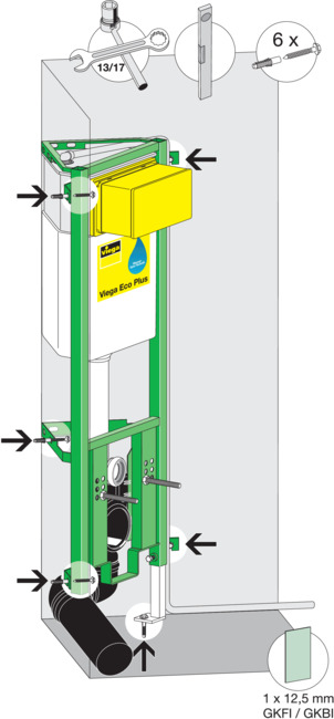
Required tools
The following tools are required for the mounting of the WC corner element:
The following tools are required for the mounting of the sink basin element:
Drill with 10 mm drill bit
Ratchet with sockets: 13 mm / 17 mm
fork or ring spanner: 13 mm / 17 mm / 19 mm
Assembly
Mounting WC element
WC mounting in a corner (approx. 90°)

-
Position the WC element at construction height.
1130 mm
980 mm
-
Align WC element.
-
Mark drill holes.

-
Drill holes for the wall fixing and the floor supports.
-
Hit dowel (10 mm) into the wall/floor.
-
Position water pipelines.

-
Screw the WC element into the wall and into the floor (SW 13).
-
Clad corner element with a single layer of IFGP (1 x 12.5 mm).
WC mounting in a corner (approx. 90°) with cladding of the drainage line

-
Position the WC element at construction height.
1130 mm
980 mm
-
Align WC element.
-
Mark drill holes (5 wall fixings and one floor support).

-
Drill holes for the wall fixing and the floor support.
-
Hit dowel (10 mm) into the wall/floor.
-
Position water pipelines.
-
Screw the WC element into the wall and into the floor (SW 13).
-
Clad corner element with a single layer of IFGP (1 x 12.5 mm).
WC mounting on the wall (one-sided fixing)

-
Position the WC element at construction height.
1130 mm
980 mm
-
Align WC element.
-
Mark drill holes (4 wall fixings and two floor supports).

-
Drill holes for the wall fixing and the floor support.
-
Hit dowel (10 mm) into the wall and the floor.
-
Position water pipelines.

-
Screw the WC element into the wall and into the floor (SW 13).
-
Clad corner element with a single layer of IFGP (1 x 12.5 mm).
Line mounting of corner elements

- * no scope of delivery
-
Position WC elements at construction height.
1130 mm
980 mm
-
Align WC elements.
-
Mark drill holes (each 4 wall fixings and two floor supports).
-
Drill holes for the wall fixing and the floor supports.
-
Hit dowel (10 mm) into the wall and the floor.
-
Position water pipelines.
-
Screw WC elements into the wall, into the floor and together (SW 13).
-
Clad corner elements with a single layer of IFGP (1 x 12.5 mm).
WC mounting in a corner >90°

-
Position the WC element at construction height.
1130 mm
980 mm
-
Align WC element.
-
Align the lugs from the WC element on the wall.
-
Mark drill holes (4 wall fixings and two floor supports).
-
Drill holes for the wall fixing and the floor support.
-
Hit dowel (10 mm) into the wall and the floor.
-
Position water pipelines.
-
Screw the WC element into the wall and into the floor (SW 13).
-
Clad corner element with a single layer of IFGP (1 x 12.5 mm).
Preparing optional actuation versions
Prepare remote actuation
The corresponding empty pipe (included in the scope of delivery of the remote actuation) is required when preparing the remote actuation Visign for Public1 (model 8326.21).

-
Lead the empty pipe from the hollow wall socket into the concealed cistern.
Distance from the remote actuation to the cistern (x)
min. 1.0 m
max. 1.7 m
Prepare electrical actuation
A corresponding empty pipe (not included in the scope of delivery of the electrical actuation) is required for the preparation of the electrical actuation (model 8350.31 or model 8350.32).

-
Lead empty pipe from the switch or button into the concealed cistern, to connect the concealed socket and concealed cistern.
Positioning of the cistern power pack
X1= max. 0.75 m
X2= max. 2.75 m with an extension cable, 1 x article number 628 505
X3= max. 4.75 m with two extension cables, 2 x article number 628 505
Setting the flush volume
INFO!
Immediate re-flushing of the flush volume is possible at the factory settings. Flush volume
Small flush volume
The WC element is factory-set at a small flush of approx. 3 l. The small flush volume can be set at three levels: approx. 3 l / 3.5 l / 4 l.
-
Remove the drain valve from the concealed cistern.

-
Push the slide control on the side of the overflow pipe to the desired small flush volume:
Top position: approx. 3 l
Middle position: approx. 3.5 l
Bottom position: approx. 4 l
The positions can be identified by the notches.
Large flush volume
The WC element is factory-set at a large flush volume of approx. 6 l. The large flush volume can be set continuously from approx. 6 l up to approx. 7.5 l.
-
Push the slide control below the drain valve to the desired large flush volume:
left: approx. 6 l
right: approx. 7.5 l
Cleaning and maintenance
Cleaning work may only be carried out by specialist trade professionals or qualified experts.
Cleaning and maintenance of the concealed cistern
In consideration of the mechanical, chemical and physical conditions, the concealed cistern is constantly contaminated.
For this reason, the components must be cleaned, as required, and the drain and filling valve seals renewed.
In areas or regions with hard water due to calcium or magnesium salts, there is the risk of limescale deposits developing on the inlet and drain valves.
The valves may have to be replaced, depending on the extent of deposits.
Disposal
Separate the product and packaging materials (e. g. paper, metal, plastic or non-ferrous metals) and dispose of in accordance with valid national legal requirements.