Grundfix Plus Control backflow trap type 3
Product information
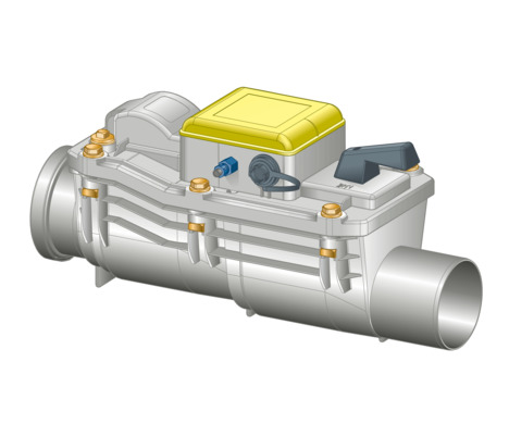
Grundfix Plus Control backflow trap type 3
for wastewater pipe containing faeces
| Year built (from): | 1. 01. 2010 |
Trade mark rights exist for this document; for further information, go to viega.com/legal .
Target groups
The information in this instruction manual is directed at the following groups of people:
Heating and plumbing experts and trained personnel
Qualified electricians
Operators
Individuals without the abovementioned training or qualification are not permitted to mount, install and, if required, maintain this product. This restriction does not extend to possible operating instructions.
The installation of Viega products must take place in accordance with the general rules of engineering and the Viega instructions for use.
Labelling of notes
Warning and advisory texts are set aside from the remainder of the text and are labelled with the relevant pictographs.

DANGER!
This symbol warns of possible life-threatening injury.

WARNING!
This symbol warns of possible serious injury.

CAUTION!
This symbol warns of possible injury.

NOTICE!
This symbol warns of possible damage to property.

INFO!
This symbol gives additional information and hints.
About this translated version
This instruction for use contains important information about the choice of product or system, assembly and commissioning as well as intended use and, if required, maintenance measures. The information about the products, their properties and application technology are based on the current standards in Europe (e.g. EN) and/or in Germany (e.g. DIN/DVGW).
Some passages in the text may refer to technical codes in Europe/Germany. These should serve as recommendations in the absence of corresponding national regulations. The relevant national laws, standards, regulations, directives and other technical provisions take priority over the German/European directives specified in this manual: The information herein is not binding for other countries and regions; as said above, they should be understood as a recommendation.
Standards and regulations
The following standards and regulations apply to Germany / Europe and are provided as a support feature.
Regulations from section: Application areas
Scope / Notice | Regulations applicable in Germany |
|---|---|
Requirements are fulfilled by Sperrfix as a type 3 backwater valve with triple backwater protection (two automatic and one manual emergency closure). Grundfix Plus Control meets the requirements as type 3 backflow trap with double backflow protection | EN 13564 |
Regulations from section: Place of installation and installation conditions
Scope / Notice | Regulations applicable in Germany |
|---|---|
Correct place of installation of the backflow trap | EN 12056 |
Securing of drainage points beneath the backflow level | DIN EN 12056‑4 |
Securing of drainage points beneath the backflow level | DIN 1986‑100 |
Requirements in backflow traps type 3 | EN 13564 |
Regulations from section: Disposal
Scope / Notice | Regulations applicable in Germany |
|---|---|
Disposal of electronic components | WEEE-Richtlinie 2012/19/EU |
Regulations from section: Inspection
Scope / Notice | Regulations applicable in Germany |
|---|---|
Monthly inspection | DIN 1986‑3 |
Safety advice
DANGER!
Danger due to electrical current
An electric shock can lead to burns and serious injury and even death.
Work on the electrical system may only be carried out by trained electricians.
When working in or on electronic systems, switch off the mains voltage and take steps to prevent accidental re-activation.
Intended use
Areas of application
The Grundfix Plus Control is operated electrically. It is suitable for use in drain pipelines with household-type wastewater carrying faecal matter (up to a temperature of 95 °C with pH values of ≥ 4 or ≤ 10).
The backflow trap is suitable for use in drain pipelines made of HT or sewer pipe DN 100, 125 or 150. When using other pipes such as e.g. clay pipes or cast-iron pipes, the relevant adapters for HT and sewer pipes must be used.
Use in industrial areas or in pipelines, which transport aggressive liquids is not permitted. This includes cleaning agents, which can damage sanitary equipment, drainage equipment and pipe materials.
Viega recommends closing the emergency trap if operation, where no wastewater is produced, is interrupted for a number of days.
Place of installation and installation conditions
According to applicable regulations, drainage points beneath the backflow level should be secured against backflow from the sewer, see Regulations from section: Place of installation and installation conditions .
A backflow trap can be used if
there is a downward slope to the sewer;
the rooms are of lower-ranking significance, i.e., neither the inhabitants' health nor major assets would be damaged if the rooms were flooded.
the system is used by a small number of people, and these people have another WC at their disposal above the backflow level which they could use in case of a backflow at the drainage object.
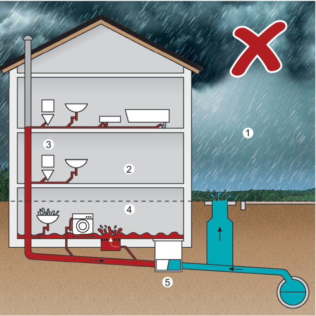
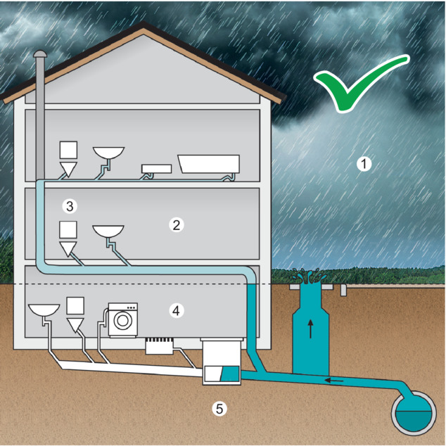
- 1 Street = Backflow level
- 2 Area safe from backflow
- 3 Connection upper floor
- 4 Area at risk of backflow
- 5 Protection against backflow through backflow trap
The connection of the upper floor (3) onto the underground pipe must be made between the backflow trap and sewer within the building (5) – only then is it possible to ensure that the wastewater system can function faultlessly. To ensure that drainage is permanently guaranteed, backflow traps may not be employed as the central safeguard for a building with drainage equipment installed above the backflow level (1) – in the event of backflow, it would lead to flooding in the building due to wastewater being unable to drain away (4).
Backflow protections and their control units should be installed in such a way that they are always accessible.
INFO!
The backflow sensor reacts at accumulation heights of 100 mm, measured from the upper edge of the base pipeline.
The installation heights of the existing floor drains, from which water could flow in the case of backflow, must therefore be taken into account during planning.
If a backflow trap is retro-fitted in a base pipeline, the height difference of 30 mm between connection pipe and coupling must be taken into account.
Maintenance
A monthly inspection must be carried out to ensure safe operation. See Inspection
Maintenance must be carried out twice a year to ensure safe operation. See Maintenance
Product description
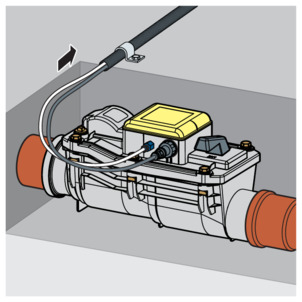
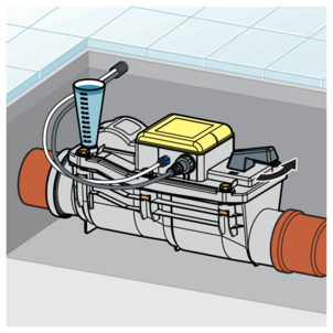
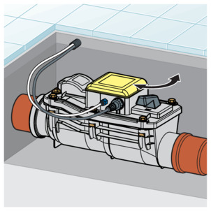
Overview
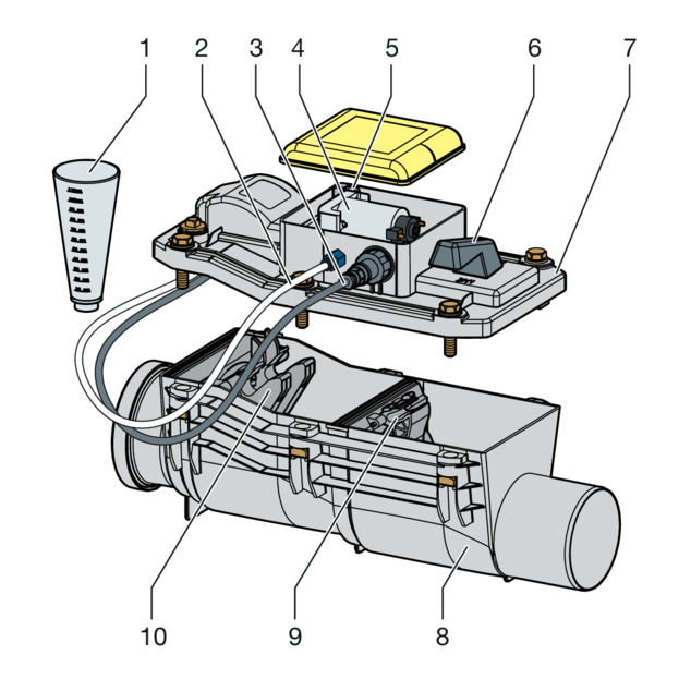
- 1 - Measuring funnel
- 2 - Pressure hose
- 3 - connection cable control
- 4 - Motor
- 5 - Pressure switch
- 6 - Emergency lock actuation
- 7 - Lid
- 8 - Casing
- 9 - Emergency lock shutter
- 10 - Motor-powered flap
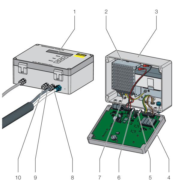
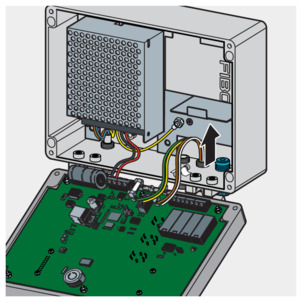
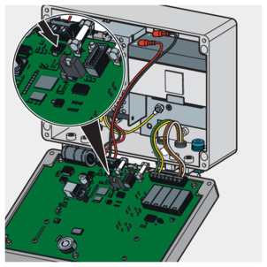
- 1 - Display
- 2 - Power pack
- 3 - Casing
- 4 - Terminal strip 15 V
- 5 - Motor fuse
- 6 - Battery fuse
- 7 - Mains supply voltage 230 V
- 8 - Pressure hose
- 9 - Connection cable
- 10 - Outlet for potential-free contacts
Technical data
Switching power pack | 88–264 VAC 50/60 Hz |
LCD | 20 x 2 with lighting |
RTC real time clock | power reserve 30 days |
rechargeable battery | 12 V 1.2 Ah integrated charge and test electronics for battery operation for up to 24 hours in the case of power failure |
Event memory | 512 events |
Potential-free relay-outlets | Back flow and fault |
Casing | Plastic casing 201 x 151 x 80 mm without hinges and PG screw fitting |
Protection class in acc. with VDE 0100 | Control casing IP54; Grundfix Plus Control IP67 |
Battery fuse | 4 A – slow |
Motor fuse | 4 A – slow |
Closing time in case of back flow | In mains or battery operation approx. 10 seconds |
Operating mode
The motor-powered flap is open during normal operation. If the pressure switch registers the backflow of water, the motor-powered flap is closed, the following display appears "Back pressure" and a signal sounds every 10 seconds. The use of the drainage equipment is not possible during this time. A battery emergency power supply ensures the functional capability of the system even when the 230 V mains power supply fails.
Using the manual actuator, the backflow trap can be closed manually and independently of the motor-powered flap.
Control elements
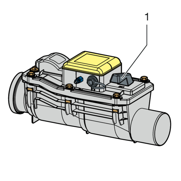
- 1 - Emergency shut-off
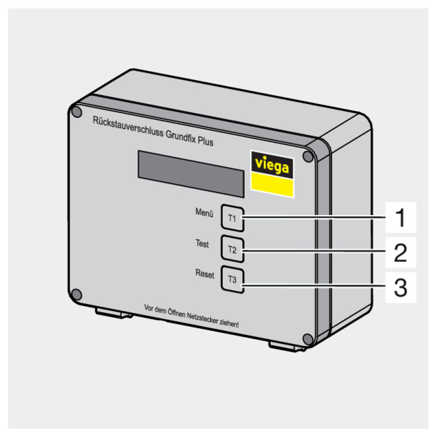
- 1 - Menu T1
- 2 - Test T2
- 3 - Reset T3
Handling
Assembly information
Installation dimensions
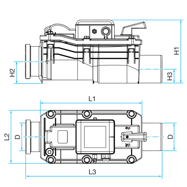
DN |
|---|
110 |
125 |
160 |
D | H1 | H2 | H3 | L1 | L2 | L3 |
|---|---|---|---|---|---|---|
110 | 260 | 100 | 65 | 405 | 215 | 545 |
125 | 260 | 105 | 75 | 405 | 215 | 550 |
160 | 295 | 125 | 95 | 470 | 245 | 640 |
INFO!
The backflow sensor reacts at accumulation heights of 100 mm, measured from the upper edge of the base pipeline.
The installation heights of the existing floor drains, from which water could flow in the case of backflow, must therefore be taken into account during planning.
If a backflow trap is retro-fitted in a base pipeline, the height difference of 30 mm between connection pipe and coupling must be taken into account.
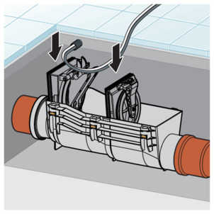
Assembly
Mounting base unit
The installation in the drainage pipeline may only be carried out by construction or specialised sanitary companies observing the building regulations and following this instruction for use.
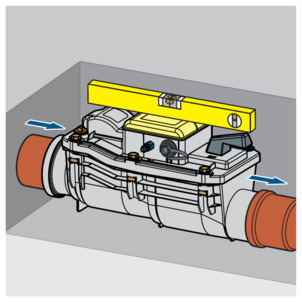
-
Install the base unit horizontally into the base pipeline.
NOTICE!Observe the flow direction!
-
At maximum, line up to the middle of the outlet pipe.
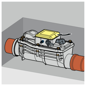
-
Close the emergency shut-off (position "ZUZU" (OFF)).
In this way, damage from flooding can be avoided before commissioning.
-
Lay the conduit pipe from the base unit to the mounting position of the control unit.
-
Close the conduit pipe at both sides using plugs.
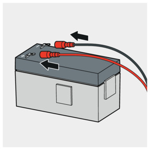
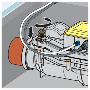
Connecting connection cable and pressure hose
INFO!
Do not loosen factory-fitted threaded cable and hose screw fittings on the casing. Otherwise, the anti-flooding function cannot be ensured.
Connecting the pressure hose
-
Loosen the union nut and push it onto the pressure hose.
-
Remove the black closing cap.
-
Tighten the union nut of the pressure hose slightly using tools.
Connecting connection cable

-
Remove the closing cap.

-
Plug in the electric plug connection straight.
NOTICE!Make sure that the plug is plugged in straight.
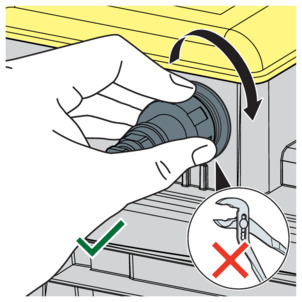
-
Tighten the union nut by hand.
INFO!The union nut must not be tightened using pliers.
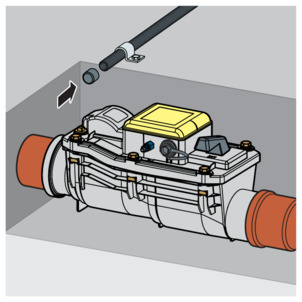
-
Lead the connection cable and the pressure hose through the empty pipe to the control. If necessary, use a cable grip device.
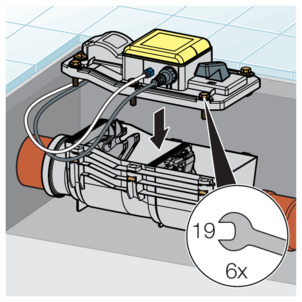
Connecting the control
DANGER!
Danger due to electrical current
An electric shock can lead to burns and serious injury and even death.
Work on the electrical system may only be carried out by trained electricians.
When working in or on electronic systems, switch off the mains voltage and take steps to prevent accidental re-activation.
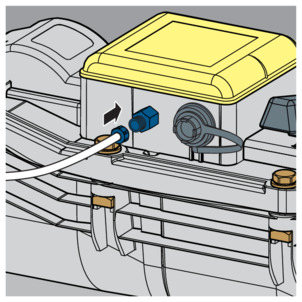
-
Fasten the control unit to the wall with four screws.

-
Connect the pressure hose to the control using the quick connection.
-
Lead the connection cable via the PG screw fitting into the internal space of the control.
-
Attach the cable ends:
black: -
red: +
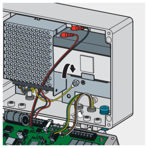
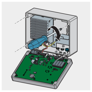
-
Insert the rechargeable battery.
-
Connect the terminal strip.
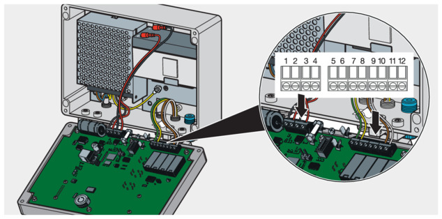
Clamping strip configuration
Pos.
cable
Functions
Marking on the connection strip
1
black – factory-fitted
15 V mains connection
GND
2
red – factory-fitted
15 V mains connection
+ 15V
3
black – factory-fitted
rechargeable battery connection
GND
4
red – factory-fitted
rechargeable battery connection
+ AKKU
5
Green
motor connection
motor -
6
Yellow
motor connection
motor +
7
signalises back flow
RÜCK (BACK)
8
signalises back flow
RÜCK (BACK)
9
signalises fault
STÖR (FAULT)
10
signalises fault
STÖR (FAULT)
11
brown
Pressure switch
Sensor
12
White
Pressure switch
Sensor
Terminal assignment 20 m cable
Pos.
cable
Functions
Marking on the connection strip
5
conductor 3
motor connection
motor -
6
conductor 4
motor connection
motor +
11
conductor 2
Pressure switch
Sensor
12
conductor 1
Pressure switch
Sensor
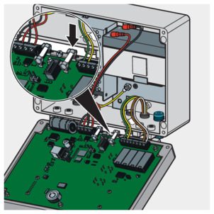
-
Insert the battery fuse (right).
INFO!On delivery, the battery fuse is attached to the inside of the casing with adhesive tape.
Depending on the length of the connection cable, a jumper may be required to make a connection onto the control. An incorrect jumper position can lead to malfunctions. Back flow protection is no longer ensured.

-
When using the cable set (20 m, art.-no. 483 500), place jumpers onto both contacts (see illustration).
-
When using cables under 8 m in length, only attach jumper to one contact (see graphic, factory condition).
Alarm and fault indicating contacts (optional)
The control unit is provided with two potential-free outlets, through which acoustic and optical alarm devices can be connected.
Both contacts function as N.O. The alarm contact (clamping strip connection 7/8) at "Rück" (Back) is closed in the event of backflow. The fault indicating contacts (clamping strip connection 9⁄10) at "Stör" (Fault) closes when an operating fault is reported.
Observe the following when connecting on-site alarm devices:
When allocating the contacts, ensure that a maximum current of 500 mA / 24 V is not exceeded.
Allocation of the outlets must only take place using safety low voltage and galvanic separation of the network.
Only connect purely ohmic loads.
The use of a safety transformer in accordance with VDE 0551 or DIN EN 60742 is permitted.
Commissioning
Commissioning the control
As soon as the mains voltage is connected, the control begins the automated commissioning process.
Display: "Commissioning"
There is a self-test of the rechargeable battery, mains connection and motor control components. The motor-powered flap is opened and closed once.
After a successful self-test, the control switches to normal operation - the motor-powered flap is opened.
Display: "Normal operation / NRV opened"
Faults detected during the self-test are shown on the screen. Errors, faults and remedy
INFO!
Date and time must be set after the initial commissioning, as a prerequisite that the maintenance reminder, error logging and daily self-test can function. Operating condition - normal operation
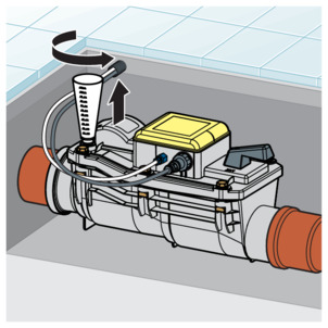
Pressure test
After commissioning of the control, the function of the pressure switch must be tested using the pressure test.

-
Set the emergency shut-off to "ZU" position.
-
Close the motor-powered flap by pressing the button T2.
-
Display readout: "Test NRV - closed"
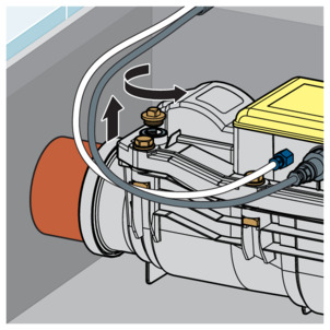
-
Unscrew the brass plug from the lid.
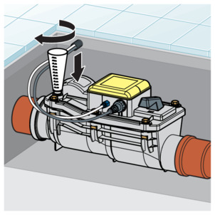
-
Screw in the test funnel.
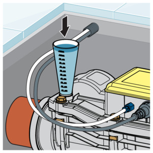
-
Fill water to the top marker of the test funnel.
-
When the pressure switch is intact, the control will report a back flow:
Display readout "Test NRV closed", "Back pressure NRV closed"
If necessary, a positive opening is possible. Press the button T3 for 5 seconds.
-
Keep the water level in the test funnel constant for 10 minutes by replenishing. Monitor the loss.
-
If the loss is greater than 0.5 l, check the seals on the flaps and replace them if necessary.
-
Set the emergency shut-off to "AUF" position.
-
The water drains away.
Display readout: "Test NRV - closed"
-
Open the motor-powered flap by pressing button T2.
-
Remove the test funnel.
-
Screw in the brass plug.
-
The control automatically changes back to normal operation after a successful procedure.
Display readout: "Normal operation / RV open"
Control
Operating conditions
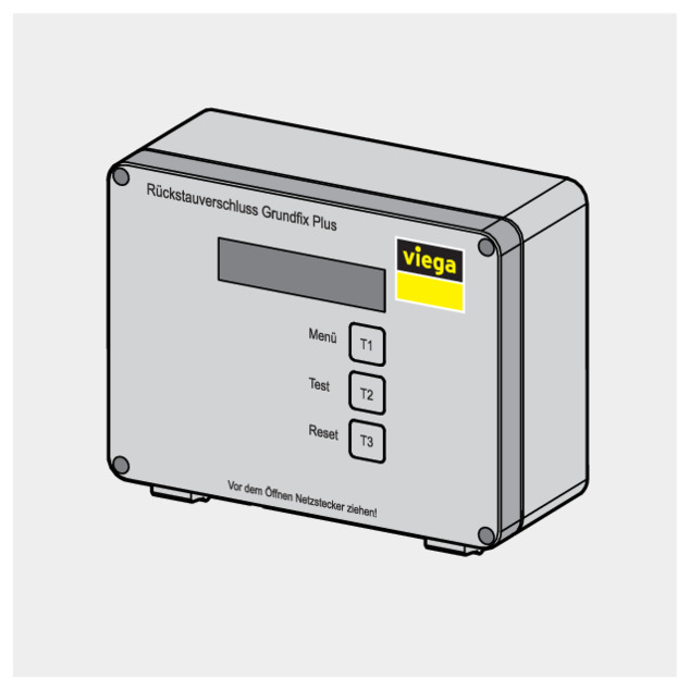
On the front of the control unit the LC display and T1, T2 and T3 buttons are located. The button functions depend on the current operating condition.
The current operating condition is shown on the display as follows:
Operating conditions
Display | Operating status | Warning signals | Operation in accordance with chapter |
|---|---|---|---|
"Normal operation" "NRV opened" | Motor-powered flap open, main supply 230 V Backflow protection is assured | – | Operating condition - normal operation |
"Back pressure" "NRV closed" | Motor-powered flap closed Backflow protection is assured | Warning signal every 10 seconds | Operating condition – back pressure |
"Back pressure" "Close emergency lock" | Suggestion to close emergency lock Risk of flooding! | Continuous signal | Operating condition – back pressure |
"Error motor fault" "NRV opened" | Pressure switch detects backflow, the motor-powered flap cannot be closed, it is blocked or the motor is defective Risk of flooding! Prompt to use the manual emergency lock. | Continuous signal | Operating condition – malfunction |
"Battery operation" "NRV opened" | Mains voltage 230 V failed Rechargeable battery has taken over the power supply Backflow protection is assured four the next 24 hours | Warning signal every 10 seconds | Operating condition – battery-powered emergency operation |
Operating condition - normal operation
Button functions in normal operation
In normal operation, control parameters can be entered and information can be called up with the T1, T2 and T3 buttons. The button functions are combined as follows:
Button | Function |
|---|---|
T1 – Menu | Scroll through menus with repeated pressing / Display ascending values in the sub-menu |
T2 – Test | Display descending values in the sub-menu |
T3 – Reset | first press = enter menu second press = exit menu and save selected value |
The available menus to set the control parameters are displayed by pressing the menu T1 button repeated on the display.
With the T3 button, you can access a menu and save and exit the menu after selecting a suitable value.
Within the menus, you can scroll up and down through the values with the T1 and T2 buttons.
Menu order in normal operation
Press T1 | The display shows | Press T3 | Press T1 | Press T2 | Press T3 | Result |
|---|---|---|---|---|---|---|
"Normal operation " "NRV opened" | ||||||
1x | "Maintenance" | Option | Motor-powered flap open/close | Return to normal operation after maintenance | Maintenance successfully completed | |
2x | "Self-test On / Off" | On / Off | On / Off | Save and return to normal operation | Self-test active/inactive | |
3x | "Time self-test adjust" | up | down | Call up one after another: Hours/Minutes | Clock set | |
4x | "Date / time adjust" Uhrzeit einstellen Datum einstellen | up | down | Call up one after another: Date/ Time | Current date/time (for log display and self-test) Note: The changeover from winter to summer time is done manually. | |
5x | "Event memory" | Back to event memory | Call up events one after another | Log display | ||
6x | "Software vers." | Back to software version | Display of current software version | |||
7x | "Operating hours" | Back to operating hours | Display operating hours | |||
8x | "Language adjust" Sprache einstellen | Select languages forward | Select languages backward | Save and return to select language | Display in selected language | |
9x | "Normal operation " "NRV opened" | Menu display starts at the beginning | ||||
"Normal operation " "NRV opened" | Press once Test backflow trap closes | Test NRV closed | ||||
Press once Test backflow trap opens | Normal operation NRV opened | |||||
"Normal operation " "NRV opened" | Press once Commissioning Backflow trap closes / Backflow trap opens | Normal operation NRV opened |
Example The unit is in normal operation and the self-test should be switched on
-
Press the T1 button until the following appears on the display: "Self-test on / off"
-
Press the T3 button – Display readout: "Off"
-
Press the T2 button – Display readout: "On"
-
Press the T3 button.
-
The setting "On" is saved.
The menu is exited. Display readout: "Normal operation"
The self-test is switched on and takes place at the predefined time.
Special functions in normal operation
Acoustic signals in case of backflow or error are switched off by pressing T1 button once and confirmed with button T3.
During normal operation, the motor-powered flap can be opened and closed by pressing the T2 button.
If no entry is made for more than one minute after pressing T1 button, the display switches to "Normal operation".
Reading of the event memory
The "Event memory" menu enables the display of 512 control unit-relevant events with date and time. When the memory is full, the oldest event is overwritten. The following events are displayed:
The display shows | Meaning |
|---|---|
"Re-init" | Reset or initialisation of the control unit |
"Motor fault" | Motor fault |
"Maintenance completed" | Successful maintenance |
"Date adjustment" | Changing of the date |
"Positive opening" | Forced opening of the motor-powered flap in case of backflow |
"NRV closes" | Motor-powered flap has been closed because the battery power is less than 11.8 V in battery operation |
"Cut-off of rechargeable battery" | System shut-down because the battery power is less than 10.5 V in battery operation |
Operating condition – back pressure
In case of a back pressure, the motor-powered flap closes.
Display readout: "Backflow NRV closed" with signal every 10 seconds.
If the backflow ends, the motor-powered flap opens and the control unit switches back to "Normal operation".
During the backflow, the buttons have the following functions:
Function | Button |
|---|---|
Switch off signal | Call up "Sound off" with T1 button and confirm with T3 button |
Force motor-powered flap to open | Keep T3 button pressed for five seconds Display readout: "Forced opening RV open" |
If the backflow sensor is defective, the motor-powered flap will remain closed even after the backflow has ended. In this case, the motor-powered flap must be forced opened.
If there is still backflow, the control will then go to "Backflow". If there is no backflow, the control will go back to "Normal operation".
Operating condition – malfunction
Mechanical faults or errors around the control are shown on the display and an acoustic alarm sounds.
During an error, the following functions can be carried out:
Function | Button |
|---|---|
Switch off signal | Press the T1 button to call up "Sound off". Confirm with the T3 button |
Remove possible closure | An initialisation is triggered with the T3 button – the motor-powered flap will open and close three times – if the error is not removed, the display will show "Fault 1 / Motor error during commissioning". |
For the procedure in case of malfunctions, see Errors, faults and remedy .
Operating condition – battery-powered emergency operation
If the power supply fails, the battery automatically takes over the main supply to the control.
Display readout: "Battery operation RV-opened"
Acoustic signal: every 10 seconds (can be switched off using T1 button).
If the rechargeable battery is fully charged (12 V), backflow is ensured for:
maximum 24 hours when using the 8 m connection cable
maximum 10 hours when using the 20 m connection cable
When the rechargeable battery charge is failing, the control unit behaves as follows:
Battery voltage below 11.8 V – motor-powered flap closes
Battery voltage below 10.5 V – control and display switch off (safeguard against total discharge). The backflow function is no longer active.
The following functions can be performed during battery emergency operation:
Button | Function |
|---|---|
T1 | Menu display |
T3 | Reset with opening and closing of the motor-powered flap |
INFO!
Maintenance is not possible during battery operation.
Errors, faults and remedy
Mechanical faults or errors are shown on the display and an acoustic alarm sounds. The error search is supported by indications on the display and is limited to a few components.
Mains adapter, rechargeable battery
Control unit
Motor, motor-powered flap with mechanism
Pressure switch
If the control unit registers a defect – during the daily self-test or due to failure of the mains or battery power – the relevant error messages are shown on the display.
NOTICE!
To avoid damage to the mechanism, button functions should only be used if the cover is firmly screwed to the Grundfix Plus-Control.
-
In the event of backflow, set the emergency shut-off to "ZU" position.
-
Repair or have faults repaired in accordance with this table:
NOTICE!If the control does not switch automatically to "Normal operation" after attempted troubleshooting, a specialist should be consulted.
The display shows | Possible cause | Troubleshooting by | Troubleshooting measures |
|---|---|---|---|
"Battery operation " "NRV opened" | Power failure, circuit breaker has activated | Operators | The power supply is automatically taken over by the battery (approx. 24 hours) until the mains voltage is restored. Safety against back flow is guaranteed.
|
"Battery error / Insert battery" | Rechargeable battery is missing or rechargeable battery fuse or cabling is defective | Trade professionals |
|
"Battery error / Replace battery" | Rechargeable battery faulty | Operators | No safeguarding against back flow in case of power outage. Replace rechargeable battery |
"Error motor fault" "NRV opened" | This error is displayed if a back flow is recognised in normal operation and the motor-powered flap cannot be closed due to an motor defect or foreign body blocking it.
| Operators | Note: In case of backflow, there is a risk of flooding – Set the emergency shut-off to "ZU" position. Trigger the self-test with T3 button:
|
"Back pressure" "Close emergency lock" | |||
"Commissioning error 1 / motor fault" | This error is displayed if a defect is recognised during a self-test.
| Operators | |
"Back pressure" "NRV closed" (Display although there is no back flow occurring) | Pressure switch defective | Operators | Positive opening with T3 button – keep pressed down for 5 seconds. Replace cover. |
| 1) | The components integrated into the cover cannot be replaced individually. |
Care and maintenance
Inspection
To ensure safe operation, a monthly inspection must be carried out by a professional, see Regulations from section: Inspection .
Check the functions of the Grundfix Plus-Control:
-
Close and re-open the motor-powered flap by pressing the button T2.
-
Actuate the emergency lock and check it for smooth function.
Maintenance
NOTICE!
To ensure safe operation, carry out maintenance of the system twice a year.
Requirements:
Maintenance is not possible in battery operation as the power loss is too great.
Maintenance must be carried out by a professional.
Only use original parts for repair, maintenance and extension.
Replace defective components, do not repair.
When using cameras and cleaning devices (cleaning spiral, high-pressure cleaner), protect the backflow trap against mechanical damage.
Only begin maintenance after ensuring that there is no backflow and the drainage objects in front of the backflow trap are being not used.
In normal operation, the control shows that maintenance is due every 4320 operating hours (=180 operating days).
Display readout: "Perform maintenance"
The acoustic signal can be switched off by pressing the buttons T1 "Sound off" and T3. The display goes off after the maintenance has completed.
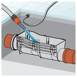
There is a pressure switch in the lid of the Grundfix Plus Control which issues the signal to close the motor-powered flap in case of back pressure. During cleaning work, the cover must not be cleaned with a high-pressure cleaner, abrasive cleaning agents, blades or similar cleaning equipment.
To avoid damage, only clean the casing, the flap mechanism and the seals with soft brushes under running water.
The buttons should only be used if the lid is firmly screwed onto the Grundfix Plus Control.
-
Choose the menu "Maintenance" by pressing button T1 and confirming with button T3.
INFO!The display remains unchanged after bringing up the "Maintenance" menu.
-
Close the motor-powered flap by pressing the button T2.
-
Set the emergency shut-off to "ZU" position.
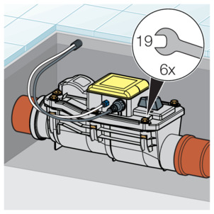
-
Loosen the screws on the lid.
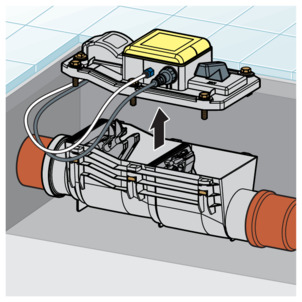
-
Carefully remove the lid.
-
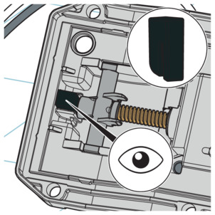
Clean the spindle on the underside of the lid.
Do not grease the spindle!
-
Check the rubber buffer on the underside of the cover and replace it if necessary.
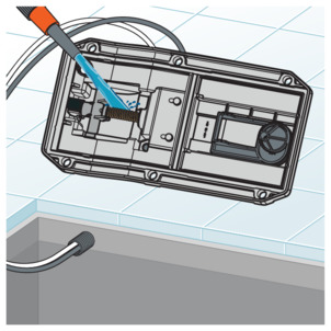
-
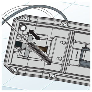
Carefully clean the opening for the pressure switch on the lower side of the lid with a small brush.
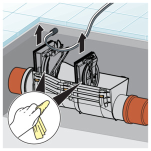
-
Take out and clean the flaps.
-
Check seals, if necessary, replace them.
-
Clean the casing.
-
The seals of the partition walls must be greased with silicon grease.
-
Install the flaps.
-
Place the lid on and screw it down.
-
Open the motor-powered flap by pressing button T2.
-
Actuate the emergency lock and check it for smooth function.
-
Set the emergency shut-off to "ZU" position.
-
Close the motor-powered flap by pressing the button T2.
-
The motor-powered flap and the emergency lock flap are closed.
-
Unscrew the brass plug from the lid.
-
Screw in the test funnel.
-
Fill water to the top marker of the test funnel.
-
When the pressure switch is intact, the control will report a back flow:
Display indication "Test NRV closed", "Back pressure NRV closed"
If necessary, a positive opening is possible. Press the button T3 for 5 seconds.
-
Keep the water level in the test funnel constant for 10 minutes by replenishing it. Observe loss.
-
If the loss is greater than 0.5 l, check the seals on the flaps and replace them if necessary.
-
Set the emergency shut-off to "AUF" position.
-
The water drains away.
Display readout: "Test NRV - closed"
-
Open the motor-powered flap by pressing button T2.
-
Remove the test funnel.
-
Screw in the brass plug.
-
The following message appears on the display after the successful procedure "Maintenance / Correctly performed".
The control returns to "Normal operation" after approx. 60 seconds.
INFO!
Alternatively, normal operation can be activated using buttons T1 and T3.
Replacing the rechargeable battery
DANGER!
Danger due to electrical current
An electric shock can lead to burns and serious injury and even death.
Work on the electrical system may only be carried out by trained electricians.
When working in or on electronic systems, switch off the mains voltage and take steps to prevent accidental re-activation.
If the rechargeable battery is faulty, it must be replaced. This will be shown on the display using the notice "Battery error/ Replace battery".
The rechargeable battery may only be replaced with an original spare part (art. no. 471 088).
-
Open the control unit.
-
Remove the defective rechargeable battery.
-
Connect the new rechargeable battery.
Clamping strip configuration
Pos.
cable
Functions
Marking on the connection strip
3
black – factory-fitted
rechargeable battery connection
GND
4
red – factory-fitted
rechargeable battery connection
+ AKKU
-
Insert the supplied battery fuse (right).
-
The charging time begins approx. 30 seconds after the rechargeable battery fuse has been inserted.
The green LED on the inside of the cover is liint
Display readout: "Battery charging"
Disposal
Separate the product and packaging materials (e. g. paper, metal, plastic or non-ferrous metals) and dispose of in accordance with valid national legal requirements.
Electronic components and batteries must not be put in the domestic waste but must be disposed of appropriately in conformity with the applicable directives, see Regulations from section: Disposal .