Multiplex drain/overflow Visign M5
Product information
Multiplex drain/overflow Visign M5
| Year built (from): | 01.06.2015 |
Trade mark rights exist for this document; for further information, go to viega.com/legal .
Target groups
The information in this instruction manual is directed at the following groups of people:
Heating and plumbing experts and trained personnel
Operators
Consumers
Individuals without the abovementioned training or qualification are not permitted to mount, install and, if required, maintain this product. This restriction does not extend to possible operating instructions.
The installation of Viega products must take place in accordance with the general rules of engineering and the Viega instructions for use.
Labelling of notes
Warning and advisory texts are set aside from the remainder of the text and are labelled with the relevant pictographs.

DANGER!
This symbol warns of possible life-threatening injury.

WARNING!
This symbol warns of possible serious injury.

CAUTION!
This symbol warns of possible injury.

NOTICE!
This symbol warns of possible damage to property.

INFO!
This symbol gives additional information and hints.
About this translated version
This instruction for use contains important information about the choice of product or system, assembly and commissioning as well as intended use and, if required, maintenance measures. The information about the products, their properties and application technology are based on the current standards in Europe (e.g. EN) and/or in Germany (e.g. DIN/DVGW).
Some passages in the text may refer to technical codes in Europe/Germany. These should serve as recommendations in the absence of corresponding national regulations. The relevant national laws, standards, regulations, directives and other technical provisions take priority over the German/European directives specified in this manual: The information herein is not binding for other countries and regions; as said above, they should be understood as a recommendation.
Intended use
Areas of application
NOTICE!
Risk of damage due to unsuitable liquids
To avoid damaging the drain, only introduce the following liquids:
Typical household wastewater with temperatures up to 95 °C
The pH value must be higher than 4 but lower than 10.
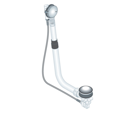
The Multiplex drain/overflow is a combined drain/overflow with optional 5 cm water level increase for bathtubs with a 52 mm drain hole.
INFO!
Please note, this model has no odour trap. A separate odour trap must be installed to complete the mounting.
The drain/overflow is suitable for bathtubs with a central drain outlet.
Detailed information regarding all bathtub models and the corresponding Viega drains/overflows can be found in the catalogue or on the Internet.
Product description
Overview
The following components are included in the scope of delivery of the Multiplex drain / overflow:
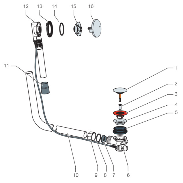
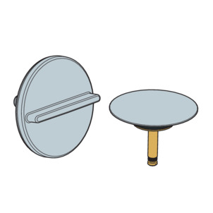
- 1 Drain plug
- 2 Fixing screw
- 3 Site protection
- 4 double seal
- 5 drain unit
- 6 Seal
- 7 Sliding ring
- 8 Union nut
- 9 Overflow pipe
- 10 Bowden cable
- 11 Coupling
- 12 Overflow unit
- 13 Profile seal
- 14 Sealing element
- 15 Fixing flange
- 16 Rotatable rosette
Technical data
Drainage capacity (at an accumulation height of 300 mm) |
|---|
Overflow capacity (at an accumulation height of 60 mm) |
Diameter of bathtub drain hole |
Threaded drain unit |
Length of Bowden cable |
Length |
Height |
Dimensions and installation depth |
The drainage capacity depends on the odour trap used. |
The overflow capacity depends on the odour trap used. |
52 mm |
1½ inch |
725 mm |
130–370 mm |
180–430 mm |
Accessories
INFO!
The accessories shown here are not included in the scope of delivery. If required, it must be purchased separately.
Optional accessories
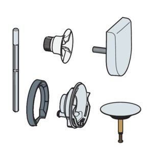
Equipment set with water level increase
The water level of the overflow can be increased by 5 cm with the equipment set. The equipment set contains a rotatable rosette, a fixing flange, a drain plug, a fixing screw, a flange cover and a mounting aid for the drain of the functional unit.
Equipment set Multiplex Visign M9: model 6171.0
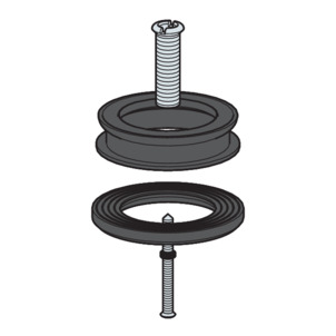
Multiplex extension set
It is possible to extend the odour trap below the bathtub in the case of bathtubs with a very thick floor. The extension set, model 6161.7, is available for such cases.
Equipment sets
If another design of the rotatable rosette and of the drain plug is required, the equipment set supplied can be exchanged for a set that is available separately.
Equipment set Multiplex Visign M3: model 6154.0
Handling
Assembly information
Mounting conditions
The following requirements exist for the mounting of the drain / overflow:
The bathtub is installed.
The drain pipeline is installed all the way to the bathtub.
The underside of the bathtub is accessible.
Installation dimensions
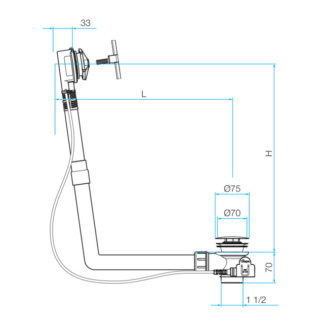
The following values are valid for L (length) and H (height):
L = 130–370
H = 180–430
Required tools and materials
Tool
socket spanner (size 14)
fine-toothed saw
flat-blade screwdriver
Material
The following material must be purchased separately and must be available during mounting:
Odour trap
Assembly
Mounting overflow
-
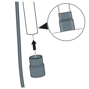
Push the rubber sleeve onto the pipe of the overflow unit.
The bottom edge must be flush with the edge of the overflow pipe.
-
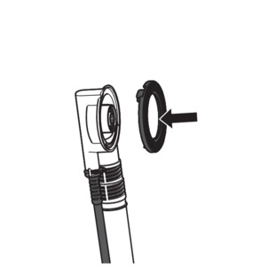
Fit the profile seal in the overflow unit.
-
Insert the sealing element into the circular slot of the fixing flange.
-
Hold the overflow unit on the overflow opening of the bathtub from the outside.
-
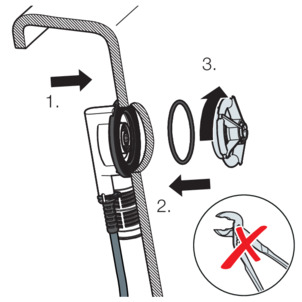
Screw the fixing flange into the overflow unit by hand.
NOTICE!Pliers or other tools may damage the fixing flange. Only turn the fixing flange by hand.
Mounting the drain
-
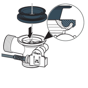
Place the double seal onto the drain unit in such a way that the recess is positioned above the connecting pipe.
-
Pull the edge of the double seal over the edge of the drain.
-
Hold the drain with the double seal onto the drain hole of the bathtub from below.
-
Pull the upper part of the double seal through the drain hole.
-
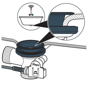
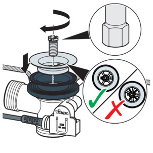
Fit the valve top in the double seal.
INFO!The cross-shaped structures of the drain unit and the valve top must be positioned parallel on top of each other to ensure the full drainage capacity.
-
Place the fixing screw in the drain unit and tighten using a socket spanner (size 14).
-
Insert the site protection.
Connecting overflow and drain
Once the overflow and drain have been installed, connect both to the overflow pipe.
Requirements:
The overflow is mounted in the overflow opening.
The drain is securely mounted on the base of the bathtub.
-
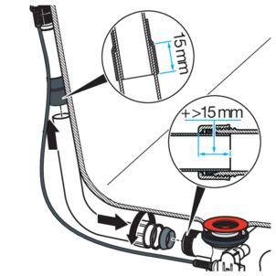
NOTICE!
Connections where the pipes are not inserted far enough into each other become leaky.
For this reason, maintain a minimum insertion depth of 15 mm for every connection.
-
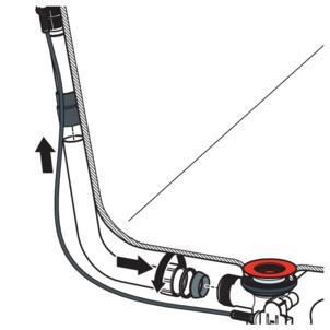
Hold the overflow pipe parallel to the pipe of the overflow unit and mark the points where the drain and overflow are connected.
Minimum insertion depth: 15 mm
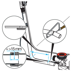
-
Cut the overflow pipe to the marked length and deburr it.
-
Push the top end of the overflow pipe into the rubber sleeve.
Minimum insertion depth: 15 mm
-
Push the union nut, sliding ring and seal onto the bottom end of the drain elbow.
-
Screw the union nut on the drain unit.
Connecting the wastewater system
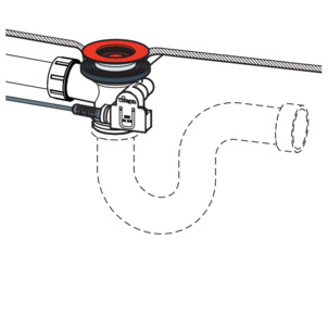
The drain unit must be connected to an external odour trap as there is no odour trap integrated into the drain fitting. The drain unit is equipped with a vertical 1½ inch threaded connection for the connection.
Requirements:
The overflow and drain units are installed on the bathtub.
The connection between overflow and drain has been made.
-
Screw the drain unit together with the on-site odour trap at the threaded connection.
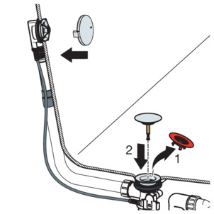
Mounting equipment set
To avoid damaging the rosette and the drain plug, do not install the equipment set until all other work has been completed:
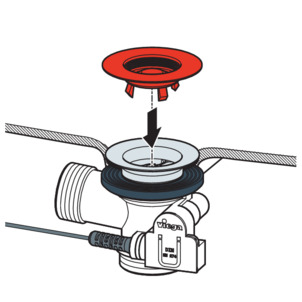
-
Align and fit the rotatable rosette.
-
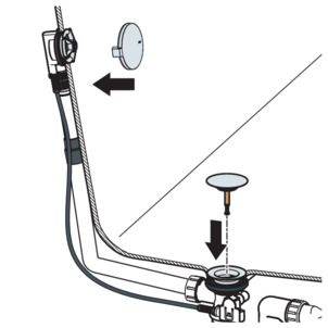
Remove the site protection.
-
Fit the drain plug.
-
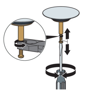
To check function and alignment, turn the rotatable rosette.
The opening of the drain plug should be 2–3 cm wide when opened. If necessary, regulate the width of the opening of the drain plug using the adjusting screw (see next step).
-
Set the drain plug with the help of the adjusting screw and counter with the nut.
Leakage test
The leakage test is only carried out as a visual inspection.
Check the points marked in the following drawing.
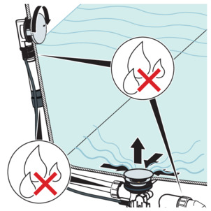
-
Check for visible leaks.
Use
The drain / overflow are controlled via the rotatable rosette on the overflow. To close or open the drain, proceed as follows:
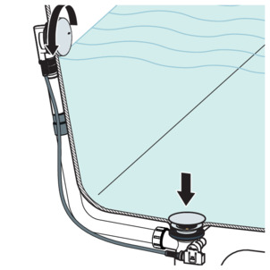
-
Turn the rotatable rosette to the left.
-
The drain closes itself.
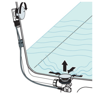
-
Turn the rotatable rosette to the right.
-
The drain opens itself.
Care
NOTICE!
Risk of damage due to unsuitable cleaning agent.
The following cleaning agents can damage chrome-plated surfaces and therefore may not be used:
scouring agent
abrasive sponges
lime, plaster or cement dissolver
solvents or other acidic cleaning agents
Use normal soap or a mild cleaning agent for regular care and prevention of lime scale on the rotatable rosette and valve cone. Do not use scouring agent or abrasive objects!
Use household cleaner to remove coarse soiling, also around the drain unit and the odour trap. Rinse the detergent thoroughly with clear water after the prescribed exposure time. There should be no residue on the components.
Disposal
Separate the product and packaging materials (e. g. paper, metal, plastic or non-ferrous metals) and dispose of in accordance with valid national legal requirements.