Fonterra Base manifold/door set 15/17, smart
Product information
Fonterra Base manifold/door set 15/17, smart
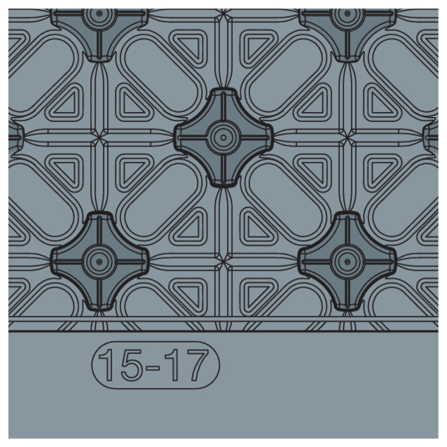
for pipe installation in doorway or manifold, Fonterra pipes d15–17
| Year built (from): | 01.05.2010 |
Trade mark rights exist for this document; for further information, go to viega.com/legal .
Target groups
The information in this instruction manual is directed at the following groups of people:
Heating and plumbing experts and trained personnel
SHK-Fachkräfte
Individuals without the abovementioned training or qualification are not permitted to mount, install and, if required, maintain this product. This restriction does not extend to possible operating instructions.
Labelling of notes
Warning and advisory texts are set aside from the remainder of the text and are labelled with the relevant pictographs.

DANGER!
This symbol warns of possible life-threatening injury.

WARNING!
This symbol warns of possible serious injury.

CAUTION!
This symbol warns of possible injury.

NOTICE!
This symbol warns of possible damage to property.

INFO!
This symbol gives additional information and hints.
About this translated version
This instruction for use contains important information about the choice of product or system, assembly and commissioning as well as intended use and, if required, maintenance measures. The information about the products, their properties and application technology are based on the current standards in Europe (e.g. EN) and/or in Germany (e.g. DIN/DVGW).
Some passages in the text may refer to technical codes in Europe/Germany. These should serve as recommendations in the absence of corresponding national regulations. The relevant national laws, standards, regulations, directives and other technical provisions take priority over the German/European directives specified in this manual: The information herein is not binding for other countries and regions; as said above, they should be understood as a recommendation.
Intended use
The elements are suitable exclusively for use in the Viega surface heating and cooling systems Fonterra Base 15‑17.
The following applications are possible:
Pipe laying in the manifold area or in doorways.
Connection of Fonterra Base system panels around doorways and for creating expansion joints.
Use as twin strips to reduce offcuts when processing Fonterra Base system panels.
Product description
Overview
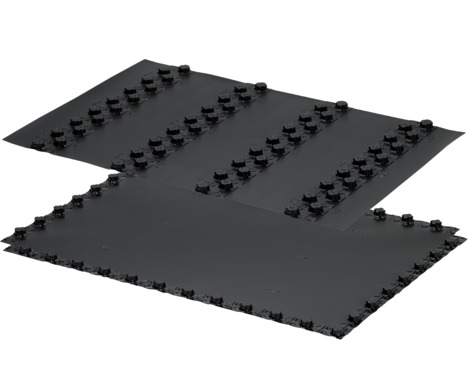
Fonterra Base-manifold / door set smart with two manifold foils and 12 door elements for on-site insulation.
Accessories
Recommended accessories:
Edge insulation strip, model 1270, 1270.1
Joint protection, modell 1273
Protective pipe for joints, model 1404
Round profile, model 1274
Technical data
Material |
|---|
Dimensions (usable size) |
Fire protection class |
Laying distance right-angled / diagonal |
- | Polystyrene |
[mm] | 1320 x 880 |
- | B2 |
[mm] | 55 / 75 |
Handling
Transport and storage
Transport
Transport in complete packing units
Storage
Store in a clean and dry place
Do not load with heavy objects
Do not remove the components from the packaging until immediately before use
General mounting instructions
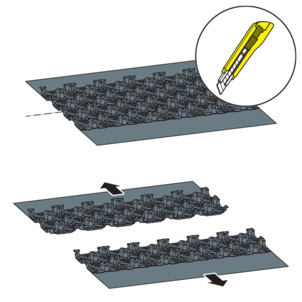
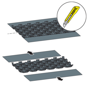
Cut the Fonterra Base door elements using a cutting knife (e.g. model 1219.8).
After laying out and applying the screed, protect from soiling and mechanical load.
Before applying the screed, carefully seal the wall connections, joints, abutting edges and any damage. When correctly installed, the overlapping Fonterra Base system panels are impermeable, even when floating screed is applied.
Install the system panels and the door elements at right angles to each other and cut exactly.
INFO!
The figures show only one of the two nap geometries as an example. Assembly is identical for the two nap geometries.
Assembly
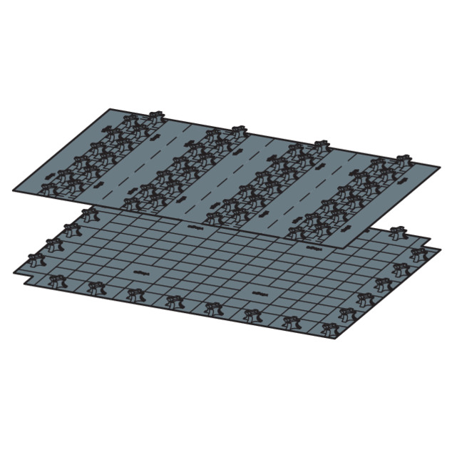
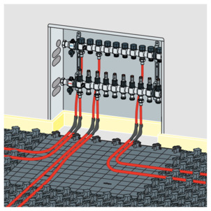
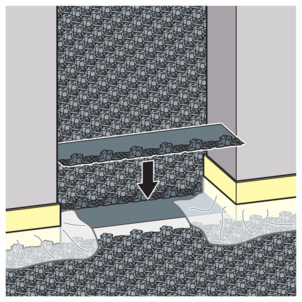
Laying the manifold element
-
Lay the manifold element in front of the manifold.
-
Connect the adjacent Fonterra Base system panels so they overlap with the manifold element.
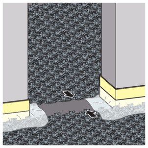
Laying the door element in the doorway
-
Cut through the door element in the centre using a cutting knife.
-
Install the Fonterra Base system panels up to the edge of the threshold.
-
If necessary, cut a suitable piece of compensating insulation and lay.
-
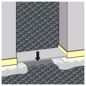
Cut the door elements to suit the width of the doorway.
-
Place the first part of the blank flush in the doorway on one side.
-
Push together in the overlapping area.
-
Place the second part of the blank flush in the doorway on the other side.
-
Push together in the overlapping area.
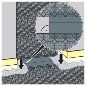
-
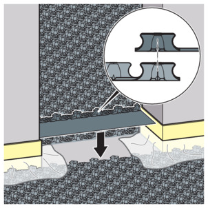
Install the system panels and the door elements at right angles to one other.
-
Place the foil of the edge insulation strip loosely on the door elements.
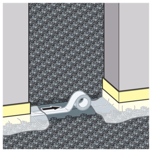
-
For flow screed, seal the edge of the overlapping door elements with adhesive tape.
-
To prevent the edge installation strip from floating when the screen is installed, fix the edge installation strip in the nap loosely using a round profile.
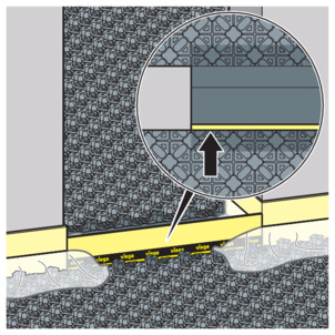
-
Optionally, create an expansion joint using an expansion joint profile (model 1275).
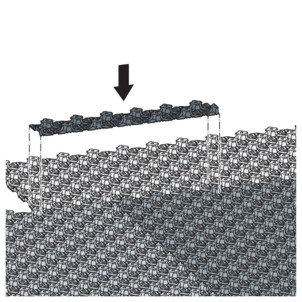
Use as twin strips
System panels can be connected without overlapping strips (remnants) using the door element cut as twin strips.
-
Trim the smooth edge area of the door element on both sides (twin strips).
-
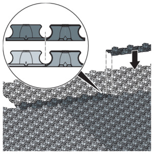
Lay the system panels against each other.
-
Carefully push the twin strips centrally onto the abutting edge.
-
The two system panels are firmly connected to one another by the twin strips.
Disposal
Separate the product and packaging materials (e. g. paper, metal, plastic or non-ferrous metals) and dispose of in accordance with valid national legal requirements.