Industry manifold DN40
Product information

Industry manifold DN40
For Fonterra radiant heating and cooling
| Year built (from): | 01.03.2008 |
Trade mark rights exist for this document; for further information, go to viega.com/legal .
Target groups
The information in this instruction manual is directed at the following groups of people:
Heating and plumbing experts and trained personnel
Individuals without the abovementioned training or qualification are not permitted to mount, install and, if required, maintain this product. This restriction does not extend to possible operating instructions.
This manual must be handed over to the operator or user after the assembly and commissioning of the product.
Labelling of notes
Warning and advisory texts are set aside from the remainder of the text and are labelled with the relevant pictographs.

DANGER!
This symbol warns of possible life-threatening injury.

WARNING!
This symbol warns of possible serious injury.
CAUTION!
This symbol warns of possible injury.

NOTICE!
This symbol warns of possible damage to property.

INFO!
This symbol gives additional information and hints.
About this translated version
This instruction for use contains important information about the choice of product or system, assembly and commissioning as well as intended use and, if required, maintenance measures. The information about the products, their properties and application technology are based on the current standards in Europe (e.g. EN) and/or in Germany (e.g. DIN/DVGW).
Some passages in the text may refer to technical codes in Europe/Germany. These should serve as recommendations in the absence of corresponding national regulations. The relevant national laws, standards, regulations, directives and other technical provisions take priority over the German/European directives specified in this manual: The information herein is not binding for other countries and regions; as said above, they should be understood as a recommendation.
Standards and regulations
The following standards and regulations apply to Germany / Europe and are provided as a support feature.
Regulations from section: Intended use
Scope / Notice | Regulations applicable in Germany |
|---|---|
Heating circuits / industry manifolds for use in heating systems | DIN EN 12828 |
Intended use
Industry manifolds are suitable for use in heating systems according to the applicable standards and guidelines for connection of heating circuits under the specified operating conditions, see Regulations from section: Intended use .
For safety reasons, arbitrary conversions or modifications of the industry manifold are not permitted.
Product description
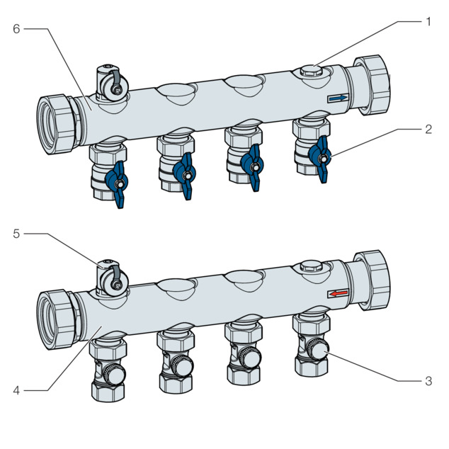
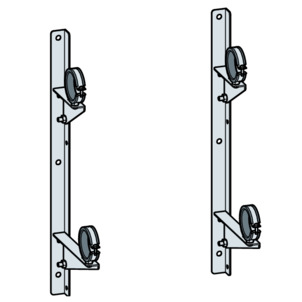
- 1 Plugs
- 2 Shut-off systems in the return flow beam
- 3 Regulation valve
- 4 Supply flow beam
- 5 Filling and drain cock
- 6 Return flow beam
Equipment:
Flat sealing
Filling/drain cock for each manifold bar
Shut-off systems in the return flow beam
Connection can be made on left or right side
Regulation valves in the supply flow beam
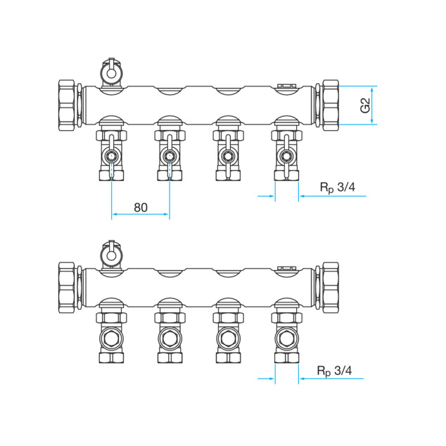
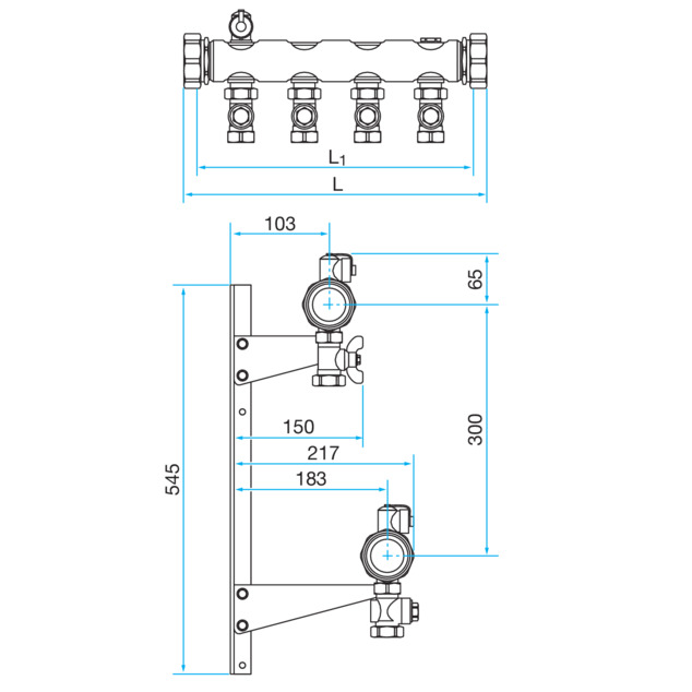
Technical data
L [mm] | Outlets | Art. no. |
|---|---|---|
395 475 555 635 715 795 875 955 1035 1115 1195 1275 1355 | 4 5 6 7 8 9 10 11 12 13 14 15 16 | 620 806 620 813 620 820 620 837 620 844 621 957 621 964 621 971 621 988 621 995 622 008 622 015 622 022 |
Material |
|---|
Maximum operating pressure |
Maximum operating temperature |
Connections |
Distance threaded connection |
Union nut |
Stainless steel |
600 kPa |
95 °C |
Rp ¾ |
80 mm |
G2 |
Accessories
Name | Short description | Art. no. |
|---|---|---|
Mounting console (model 1299) |
| 613 082 |
Handling
Transport and storage
Observe the following with transport and storage:
Avoid heavy blows and vibrations.
Store the components in a clean and dry place.
Do not remove the components from the packaging until immediately before use.
General mounting instructions
The manifold can be mounted in vertical position, with outlet facing up or down, or in horizontal position at a storey floor.
Always depressurize and cool the system before doing any installation and maintenance work.
The mounting consoles are available as accessories.
The filling and drainage valve is suitable for connecting Viega hose screw fittings, article no. 117 696 and 109 073.
Assembly
-
Assemble the supply flow beam, the return flow beam, and the mounting console (available separately).
NOTICE!Align the supply and return flow beam centrally to one another.
-
Fasten the industry manifold to the wall or ceiling.
-
Check the valve casing for contamination and damage.
-
Connect the pipes.
-
Use Viega screw fittings or press connectors to connect the pipes.
-
Flush the system and perform a leakage test before commissioning.
Settings
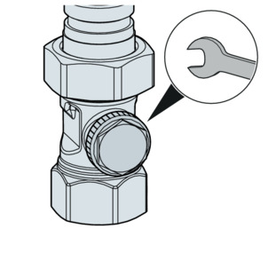
Shutting valves off
-
Unscrew the closing cap using a size 19 fork spanner.
-
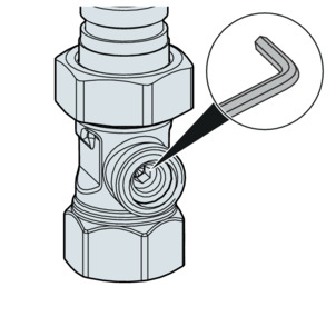
Turn the size 5 Allen key clockwise to close the return pipe screw fitting.
-
Unscrew the closing cap and tighten it with max. 15 Nm using a size 19 fork spanner.
-
To open the screw fitting, turn the screw fitting anti-clockwise at most until you can feel a resistance.
-
If the screw fitting has been set for hydraulic balancing, determine the respective number of revolutions during the tightening process.
INFO!This ensures that the original setting can be restored.
Regulating valves
-
Unscrew the closing cap using a size 19 fork spanner.
-
Turn the size 5 Allen key clockwise to close the return pipe screw fitting.
-
Adjust to the specified setting by turning the size 5 Allen key anti-clockwise.
INFO!Determine the adjustment revolutions by way of the diagram.
-
Screw on the closing cap.
-
Tighten the closing cap with the size 19 fork spanner with max. 15 Nm.
Pressure loss diagram regulation valve
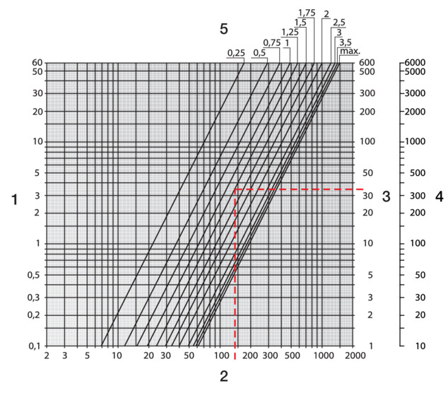
- 1 Pressure loss Δp [kPa]
- 2 Mass flow m
- 3 Pressure loss Δp [hPa]
- 4 Pressure loss Δp [mm WS]
- 5 Number of revolutions [U]
Kv value [m3 / h]
Number of revolutions [U] | Kvs value [m3 / h] | ζ value (open) | |||||||
|---|---|---|---|---|---|---|---|---|---|
0.25 | 0.5 | 1 | 1.5 | 2 | 2.5 | 3 | 3.5 | ||
0.22 | 0.37 | 0.62 | 0.92 | 1.27 | 1.55 | 1.72 | 1.85 | 1.93 | 93.2 |
Disposal
Separate the product and packaging materials (e. g. paper, metal, plastic or non-ferrous metals) and dispose of in accordance with valid national legal requirements.