Viega Eco Plus washbasin element
with concealed connection box
Product information
Viega Eco Plus washbasin element
with concealed connection box
for a washbasin with a single-hole fitting
| Year built (from): | 01.07.2015 |
Trade mark rights exist for this document, further information can be found at viega.com/legal .
Target groups
The information in this instruction manual is directed at the following groups of people:
Heating and sanitary professionals and trained personnel
SHK-FachkräfteDrywall builder
It is not permitted for individuals without the abovementioned training or qualification to mount, install and, if required, maintain this product. This restriction does not extend to possible operating instructions.
The installation of Viega products must take place in accordance with the general rules of engineering and the Viega instructions for use.
Labelling of notes
Warning and advisory texts are set aside from the remainder of the text and are labelled with the relevant pictographs.

DANGER!
This symbol warns against possible life-threatening injury.

WARNING!
This symbol warns against possible serious injury.

CAUTION!
This symbol warns against possible injury.

NOTICE!
This symbol warns against possible damage to property.

INFO!
Notes give you additional helpful tips.
About this translated version
This instruction for use contains important information about the choice of product or system, assembly and commissioning as well as intended use and, if required, maintenance measures. The information about the products, their properties and application technology are based on the current standards in Europe (e. g. EN) and/or in Germany (e. g. DIN/DVGW).
Some passages in the text may refer to technical codes in Europe/Germany. These should serve as recommendations in the absence of corresponding national regulations. The relevant national laws, standards, regulations, directives and other technical provisions take priority over the German/European directives specified in this manual: The information herein is not binding for other countries and regions; as said above, they should be understood as a recommendation.
Standards and regulations
The following standards and regulations apply to Germany / Europe. National regulations can be found on the relevant web site of your country at viega.com/standards .
Regulations from section: Fields of application / Mounting conditions
Scope / Notice | Regulations applicable in Germany |
|---|---|
suitable masonry walls | EN 1996‑1‑1 |
suitable concreted walls | DIN 1045 |
suitable support profiles | DIN 18183 |
Regulations from section: Sound protection
Scope / Notice | Regulations applicable in Germany |
|---|---|
Fulfilled noise protection requirements | DIN 4109 |
Fulfilled noise protection requirements | DIN 4109 (additional sheet 2) |
Fulfilled noise protection requirements | VDI 4100 SSt I-SSt II |
Product description
Overview

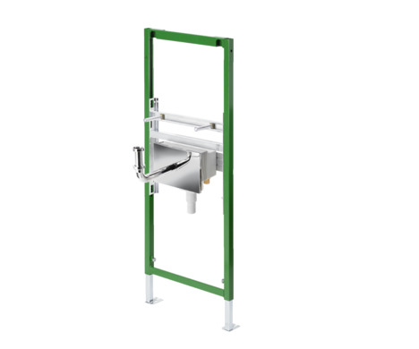
- 1 - Viega Eco Plus element
- 2 - washbasin module
- 3 - threaded bolt
- 4 - concealed connection box
- 5 - drain elbow
- 6 - adjustable feet
Compatible components
The element is compatible with all common washbasin ceramics, even with larger projection (barrier-free).
Sound protection
The washbasin element complies with the noise insulation requirements specified in section Regulations from section: Sound protection .
Technical data
The product has the following technical data:
Rubber nipple |
|---|
Hole diameter for fixing in wooden frame construction |
Construction height |
DN 40 / 30 |
11 mm |
1130 mm |
Accessories
Required accessories

The fixing set model 8173 is required to secure.
Handling
Assembly information
Mounting conditions
Suitable walls
The element is suitable for mounting on masonry wall constructions and support profiles pursuant to the regulations in section Regulations from section: Fields of application / Mounting conditions .
The element may only be mounted on even wall surfaces.
Construction height
With the construction height, the marked height of the upper edge of the finished floor must be observed.
Installation dimensions

Required tools
The following tools are required for mounting the washbasin element:
drill with 10 mm drill bit
ratchet with sockets: 13 mm / 17 mm
fork or ring spanner: 13 mm / 17 mm
Assembly
Mounting the element
Preparing concealed connection box

-
Seal corner valve or seal with hemp.

-
Screw the corner valve into the screw fitting.

-
Seal and screw in a suitable pipeline adapter.

-
INFO!
Observe the additional markings when aligning the corner valves.
Screw in until the connection to the washbasin fitting is between the markings.

-
Mount the entire seats in the concealed connection box.

-
The object can be heard locking into place.
Masonry wall
INFO!
Masonry and concreted walls
You should use a support bracket (model 8165) when mounting multiple washbasin elements with an interval of > 490 mm. Observe the instructions for use of the support bracket when mounting.

-
Determine and mark fixing points.
X1: 390 mm (model 8180.73)
X2: 440 mm (model 8173)
X3: 1100 mm

-
Drill holes.
-
Mount the fixing set with the fork spanner (size 13).

-
Align height of element.
Whilst doing so, observe the markings on the element.
Determine construction height in accordance with the on-site marking of the upper edge of the finished floor.
x = Observe the instructions of the washbasin manufacturer.
INFO!The construction height must be determined exactly.
There are only limited possibilities available to remedy errors made during this assembly step, Construction height .

-
Set the installation depth of the element with the fork spanner (size 17).

-
Remove WC element and drill floor holes.

-
Attach element to the floor using the fork spanner (size 13) and the screws and dowels supplied.

-
Adjust the height of the washbasin support.

-
Mount concealed connection box in the washbasin support.
Secure with the fixing material supplied.
-
Check all dimension settings.

-
Make water connections.

-
Double-clad element (2 x 12.5 mm).
Finishing work on the concealed connection box, see instructions for use of the model 8055.5.
Mounting in on-site support profile
The element can be inserted into the 50 mm and 75 mm support profiles.
-
Determine the fixing points.
-
Align element.
-
Mount threaded bolts.
-
Pre-mount concealed connection box Preparing concealed connection box .

-
Adjust the height of the washbasin support.

-
Mount concealed connection box in the washbasin support.
Secure with the fixing material supplied.
-
Check all dimension settings.

-
If necessary, adjust the pre-mounted foot depth from 75 mm to 50 mm: Pull out foot and turn by 90°.

-
Attach element to the floor using the fork spanner (size 13) and the screws and dowels supplied.
-
Determine construction height in accordance with the on-site marking of the upper edge of the finished floor.
-
Align height of element.
Whilst doing so, observe the markings on the element.
INFO!The construction height must be determined exactly.
There are only limited possibilities available to remedy errors made during this assembly step, Construction height .

-
Screw element together laterally with the support profiles.

-
Make water connections.

-
Double-clad element (2 x 12.5 mm).
Finishing work on the concealed connection box, see instructions for use of the model 8055.5.
Final assembly of the concealed connection box

-
Remove site protection.
-
Cut the shaft of the concealed connection box flush with tiles.

-
Manufacture the connection for the washbasin fitting on one side above the copper pipe supplied.
If necessary, the chrome-plated pipe elbow supplied must be cut to the corresponding length.

-
Manufacture the second connection on the other side in the same way.

-
Shorten copper pipe. The connection of the compression screw fitting must be within the concealed connection box.
-
Attach compression screw fitting.

-
Optionally, the washbasin fitting can also be connected to the concealed connection box using flexible hoses.

-
Align corner valves.
When doing so, align the pipe elbow to the marking aid (line on the concealed connection box).

-
Insert the drain elbow into the lip seal of the odour trap.
-
Identify sizes on the drain elbow and adjusting pipe that may have to be shortened.
The sizes are marked in the diagram with X and are dependent on the chosen washbasin fitting.

-
Deburr cut edge.
Grease lip seal.
-
Insert the drain elbow through the cover plate in the lip seal of the odour trap.

-
Set the odour trap to the right size at the height.
The vertical setting range is 20 mm.

-
Attach the cover plate to the concealed connection box.
The lateral supports serve as a safeguard against distortion.

-
Turn the drain elbow to the right and in doing so secure it to the washbasin.
When doing so, check for leaks.
Optional cable inlet
On the top of the concealed connection box a section can be cut out which, for example, can be used as a cable passage.

-
Cut out and remove the area with a cutting knife.
-
Lead the cable through the opening and secure.
Cleaning and maintenance
Replacing corner valves

-
Cut the water supply.
-
When replacing the corner valve, counter the screw fitting with a spanner (size 27).
Disposal
Separate the product and packaging materials (e. g. paper, metal, plastic or non-ferrous metals) and dispose of in accordance with valid national legal requirements.