Gasskuleventil med teståpning
Produktinformasjon
Gasskuleventil med teståpning
| Produksjonsår (fra): | 15.11.2007 |
Dette dokumentet er beskyttet av opphavsrett, ytterligere informasjon får du på viega.com/legal .
Målgrupper
Informasjonen i denne anvisningen retter seg til følgende grupper:
Installasjonsbedrifter
Fagbedrifter for konstruksjon, vedlikehold og endring av jordgass- eller flytende gass-anlegg
Flytende gass-anlegg må kun legges, vedlikeholdes eller endres av fagbedrifter med nødvendig fagkunnskap og erfaring.
Personer som ikke har denne utdannelsen hhv. kvalifikasjonene, har ikke tillatelse til å montere, installere og evt. vedlikeholde disse produktene. Denne begrensningen gjelder ikke for eventuelle merknader om betjening.
Installasjon av Viega-produkter skal skje iht. generelle, anerkjente regler for dette fagområdet og Viega-bruksanvisningene.
Merking av instruksjoner
Advarsels- og merknadstekster er uthevet fra resten av teksten og spesielt merket med egne piktogrammer.

FARE!
Advarer mot mulige livsfarlige personskader.

ADVARSEL!
Advarer mot mulige alvorlige personskader.

FORSIKTIG!
Advarer mot mulige personskader.

MERKNAD!
Advarer mot mulige materielle skader.

INFO!
Ytterligere merknader og tips.
Merknader til denne språkversjonen
Denne bruksanvisningen inneholder viktig informasjon om produkt- eller systemvalg, montering og igangkjøring, samt om tiltenkt bruk og, om nødvendig, om vedlikeholdstiltak. Denne informasjonen om produkter, deres egenskaper og bruksteknikk er basert på de aktuelle gjeldende standardene i Europa (f.eks. EN) og/eller i Tyskland (f.eks. DIN/DVGW).
Noen passasjer i teksten kan henvise til tekniske forskrifter i Europa/Tyskland. Disse forskriftene gjelder som anbefalinger for andre land, i den grad det der ikke finnes tilsvarende, nasjonale krav. Gjeldende nasjonale lover, standarder, forskrifter, normer samt andre tekniske forskrifter har prioritet foran de tyske/europeiske retningslinjene i denne veiledningen: Informasjonen her er ikke bindende for andre land og områder, og skal som sagt brukes som støtte.
Normer og regelverk
De følgende normer og regelverk gjelder for Tyskland hhv. Europa og skal forstås som et hjelpegrunnlag.
Regelverk fra avsnittet: Bruksområde
Gyldighetsområde / Merknad | Regelverk som gjelder i Tyskland |
|---|---|
Planlegging, utførelse, endring og drift av gassinstallasjoner | DVGW-TRGI 2018 |
Planlegging, utførelse, endring og drift av LPG-installasjoner | DVFG-TRF 2021 |
Gassinstallasjoner for industrielle, kommersielle og kjøretøytekniske anlegg | DVGW-Arbeitsblatt G 5614 |
Gassinstallasjoner for industrielle, kommersielle og kjøretøytekniske anlegg | DVGW-Arbeitsblatt G 462 |
Gassinstallasjoner for industrielle, kommersielle og kjøretøytekniske anlegg | DVGW-Arbeitsblatt G 459‑1 |
Gassinstallasjoner for industrielle, kommersielle og kjøretøytekniske anlegg | DVGW Fachinformation Nr. 10 |
Gassinstallasjoner for industrielle, kommersielle og kjøretøytekniske anlegg | DVGW-TRGI 2018 |
Regelverk fra avsnittet: Medier
Gyldighetsområde / Merknad | Regelverk som gjelder i Tyskland |
|---|---|
Gasspesifikasjoner | DVGW-Arbeitsblatt G 260 |
Regelverk fra avsnittet: Oversikt
Gyldighetsområde / Merknad | Regelverk som gjelder i Tyskland |
|---|---|
Krav til gasskoblinger | DIN EN 331 |
Tetthetskriterier | DIN 3537‑1 |
Regelverk fra avsnittet: Gjengeforbindelse
Gyldighetsområde / Merknad | Regelverk som gjelder i Tyskland |
|---|---|
Gjengeparing | DIN EN 10226‑1 |
Tillatt tetningsmiddel | DIN 30660 |
Tillatt tetningsmiddel | DIN EN 751‑2 |
Regelverk fra avsnitt: Tekniske data
Gyldighetsområde / Merknad | Regelverk som gjelder i Tyskland |
|---|---|
Driftstemperatur | DIN EN 331 |
Regelverk fra avsnittet: Korrosjon
Gyldighetsområde / Merknad | Regelverk som gjelder i Tyskland |
|---|---|
Korrosjonsbeskyttelse | DIN 30672 |
Korrosjonsbeskyttelse for utendørs ledninger | DVGW-TRGI 2018, Punkt 5.2.7.1 |
Korrosjonsbeskyttelse for innendørs ledninger | DVGW-TRGI 2018, Punkt 5.2.7.2 |
Korrosjonsbeskyttelse for utendørs ledninger | DVFG-TRF 2021, Punkt 7.2.7.2 |
Korrosjonsbeskyttelse for innendørs ledninger | DVFG-TRF 2021, Punkt 7.2.7.3 |
Regelverk fra avsnittet: Monteringsanvisninger
Gyldighetsområde / Merknad | Regelverk som gjelder i Tyskland |
|---|---|
Gassinstallasjoner | DVGW-TRGI 2018 |
Unntak, utvalgskriterier og anordning av komponenter | DVGW-TRGI 2018 |
LPG-installasjoner | DVFG-TRF 2021 |
Unntak, utvalgskriterier og anordning av komponenter | DVFG-TRF 2021 |
Bruk av aktive beskyttelsestiltak | DVGW-TRGI 2018, punkt 5.3.6.3.1 |
Bruk av passive beskyttelsestiltak | DVGW-TRGI 2018, punkt 5.3.6.3.2 |
Regelverk fra avsnittet: Lekkasjetest
Gyldighetsområde / Merknad | Regelverk som gjelder i Tyskland |
|---|---|
Lekkasjetest av gassinstallasjoner | DVGW-TRGI 2018, punkt 5.6 |
Lekkasjetest for LPG-installasjoner | DVFG-TRF 2021, punkt 8.2 |
Regelverk fra avsnittet: Vedlikehold
Gyldighetsområde / Merknad | Regelverk som gjelder i Tyskland |
|---|---|
Sikre og opprettholde driftssikker tilstand | DVGW-TRGI 2018 Punkt 13 |
Tiltenkt bruk
INFO!
Bruk av modellene til andre bruksområder og medier enn de som er beskrevet, må avtales med Viega.
En kuleventil er en armatur som ved en 90°-bevegelse kan stenge av og åpne enkelte rørledningsavsnitt. Kuleventilen er ingen reguleringsarmatur og kan ikke brukes til regulering av volumstrømmer, for det er ikke tillatt å sette kulen i en mellomstilling.
Bruksområder
Bruk er bl.a. mulig i følgende områder:
gassinstallasjoner
LPG-installasjoner
For planlegging, utførelse, endring og drift av gassinstallasjoner må gjeldende retningslinjer følges, se Regelverk fra avsnittet: Bruksområde .
Bruk er mulig i følgende beskrevne gassinstallasjoner:
gassinstallasjoner
Lavtrykksområde ≤ 100 hPa (100 mbar)
Mellomtrykkområde fra 100 hPa (100 mbar) til 0,1 MPa (1 bar)
LPG-installasjoner
med LPG-tank i mellomtrykkområdet etter trykkregulatorventilen, 1. trinn på LPG-tank > 100 hPa (100 mbar) opp til et tillatt driftstrykk på 0,5 MPa (5 bar)
med LPG-tank i lavtrykksområdet ≤ 100 hPa (100 mbar) etter trykkregulatorventilen, 2. trinn
med LPG-trykkbeholder (LPG-flasker) < 16 kg
etter småflaske-trykkreguleringsventilen
med LPG-tank (LPG-flaske) ≥ 16 kg
etter storflaske-trykkreguleringsapparat
Følg gjeldende retningslinjer, se Regelverk fra avsnittet: Bruksområde .
Medier
Modellen er bl.a. egnet for følgende medier:
Gass, se Regelverk fra avsnittet: Medier
LPG, kun i gassformig tilstand for bruk i boliger og kommersielle bygninger, se Regelverk fra avsnittet: Medier .
Produktbeskrivelse
Oversikt
INFO!
Viega gasskoblinger tilsvarer kravene til gjeldende retningslinjer. Gasskoblingene er kontrollert og godkjent av DVGW for følgende kriterier, se Normer og regelverk :
Tetthet
Høy termisk motstand (HTB)
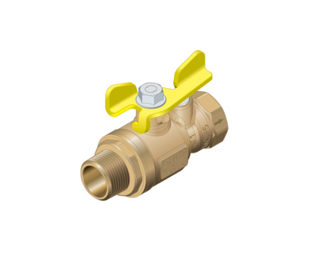
Modellen er utstyrt på følgende måte:
Hus av rødgods/silisiumbronse
Utvendige R-gjenger
Innvendige Rp-gjenger
Teståpning < 1 mm
Testskrue i dimensjonen G ⅛
Gult, pulverbelagt T-håndtak av metall, 90° dreibart
Modellen er plomberbar og kan i tillegg låses med en standard hengelås.
Modellen er tilgjengelig i følgende dimensjon: R / Rp ¾.
Gjenget tilkobling
Forutsetningen for en gjenget tilkobling, som tetter via gjengene, er en paring av gjenger iht. gjeldende retningslinjer, se Regelverk fra avsnittet: Gjengeforbindelse . I henhold til disse forskriftene består en tillatt gjengeparing av koniske utvendige gjenger og sylindriske innvendige gjenger, f. eks. R ¾ og Rp ¾.
Til tetning av gjenger skal det kun brukes standard og kloridfrie, DVGW-godkjente tetningsmidler iht. gjeldende retningslinjer, se Regelverk fra avsnittet: Gjengeforbindelse .
Merkinger på komponenter
Modellen er merket på følgende måte:
MOP5 for maksimalt driftstrykk 0,5 MPa (5 bar)
GT1 for maksimalt driftstrykk ved HTB-krav 0,1 MPa (1 bar)
DVGW-påskrift
HTB-merking
Kompatible komponenter
Hvis du har spørsmål om dette temaet, kan du også henvende deg til Viega servicesenter.
Tekniske data
Overhold de følgende driftsbetingelser for installasjonen av modellen:
Anvendelse |
|---|
Driftstemperatur |
Driftstrykk |
Gassinstallasjon | LPG-installasjon |
|---|---|
-20–70 °C | -20–70 °C |
≤ 0,5 MPa (5 bar) (MOP5) ≤ 0,1 MPa (1 bar) (HTB / GT1)2) | ≤ 0,5 MPa (5 bar) (MOP5)1) ≤ 0,1 MPa (1 bar) (HTB / GT1)2) |
| 1) | Maksimalt trykk – tilsvarer utløsningstrykket til SAV i trykkregulatorventilen |
| 2) | Driftstrykk ved HTB-krav maks. 0,1 MPa (1 bar) (GT1) |
I henhold til gjeldende retningslinjer ligger gyldighetsområdet for driftstemperaturen mellom -20 °C og 60 °C, se Normer og regelverk .
Håndtering
Monteringsinformasjoner
Monteringsanvisninger
Kontrollere systemkomponenter
Ved transport og lagring kan systemkomponenter evt. ha blitt skadet.
Kontroller alle delene.
Skift skadede komponenter.
Ikke reparer skadede komponenter.
Skitne komponenter skal ikke installeres.
Monteringsbetingelser
Vær oppmerksom på følgende ved monteringen:
Modellen må ikke tildekkes eller males.
Modellen må ikke installeres i varmesoner (f. eks. med varme avgasser eller sterk varmestråling).
Bruk egnet verktøy.
Unntak, utvalgskriterier og anordningen av komponentene er beskrevet i de gjeldende retningslinjene, se Normer og regelverk .
MERKNAD!
Sørg for aktive og evt. passive sikkerhetstiltak for å beskytte en gassinstallasjon mot inngrep fra uvedkommende.
Sørg prinsipielt for aktive sikkerhetstiltak.
Velg passive sikkerhetstiltak avhengig av installasjonen og bruk de.
Bruk av aktive og passive sikkerhetstiltak er regulert i gjeldende retningslinjer, se Normer og regelverk .
Vedlikehold
Gassinstallasjoner må kontrolleres visuelt en gang i året, f.eks. av operatøren.
Bruksegnethet og tetthet må kontrolleres hvert 12. år av en installasjonsbedrift.
For å garantere og overholde driftssikker tilstand må gassinstallasjonene drives og holdes i stand forskriftsmessig. Du finner detaljert informasjon om dette i de gjeldende retningslinjene, se Regelverk fra avsnittet: Vedlikehold .
Kassering
Del opp produkt og emballasje i de enkelte materialgruppene (f.eks. papir, metall, plast eller ikke-jern-metaller) og kasser i henhold til gjeldende nasjonal lovgiving.