Viega Eco Plus bidet corner element
Product information
Viega Eco Plus bidet corner element
for wall-hung bidet
| Year built (from): | 01.09.2005 |
Trade mark rights exist for this document, further information can be found at viega.com/legal .
Target groups
The information in this instruction manual is directed at the following groups of people:
Heating and sanitary professionals and trained personnel
SHK-Fachkräfte
It is not permitted for individuals without the abovementioned training or qualification to mount, install and, if required, maintain this product. This restriction does not extend to possible operating instructions.
The installation of Viega products must take place in accordance with the general rules of engineering and the Viega instructions for use.
Labelling of notes
Warning and advisory texts are set aside from the remainder of the text and are labelled with the relevant pictographs.

DANGER!
This symbol warns against possible life-threatening injury.

WARNING!
This symbol warns against possible serious injury.

CAUTION!
This symbol warns against possible injury.

NOTICE!
This symbol warns against possible damage to property.

INFO!
Notes give you additional helpful tips.
About this translated version
This instruction for use contains important information about the choice of product or system, assembly and commissioning as well as intended use and, if required, maintenance measures. The information about the products, their properties and application technology are based on the current standards in Europe (e. g. EN) and/or in Germany (e. g. DIN/DVGW).
Some passages in the text may refer to technical codes in Europe/Germany. These should serve as recommendations in the absence of corresponding national regulations. The relevant national laws, standards, regulations, directives and other technical provisions take priority over the German/European directives specified in this manual: The information herein is not binding for other countries and regions; as said above, they should be understood as a recommendation.
Standards and regulations
The following standards and regulations apply to Germany / Europe. National regulations can be found on the relevant web site of your country at viega.com/standards .
Regulations from section: Fields of application / Mounting conditions
Scope / Notice | Regulations applicable in Germany |
|---|---|
suitable masonry walls | EN 1996‑1‑1 |
suitable concreted walls | DIN 1045 |
suitable support profiles | DIN 18183 |
Regulations from section: Sound protection
Scope / Notice | Regulations applicable in Germany |
|---|---|
Fulfilled noise protection requirements | DIN 4109 |
Fulfilled noise protection requirements | DIN 4109 (additional sheet 2) |
Fulfilled noise protection requirements | VDI 4100 SSt I-SSt II |
Product description
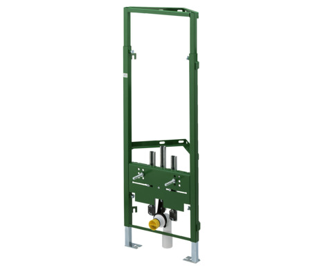
Overview

- 1 - Viega Eco Plus corner element
- 2 - threaded rods for fixing sanitary objects (gauges for bore hole 180 mm and 230 mm)
- 3 - mounting bracket for drain elbow
- 4 - drain elbow
- 5 - adjustable feet
- 6 - mounting bracket for wall plate
Sound protection
The bidet element complies with the noise insulation requirements specified in section Regulations from section: Sound protection .
Handling
Assembly information
Mounting conditions
Suitable walls
The Viega bidet element is suitable for mounting on masonry wall constructions and support profiles pursuant to the regulations in section Regulations from section: Fields of application / Mounting conditions .
The bidet element may only be mounted on even wall surfaces.
Construction height
With the construction height, the marked height of the upper edge of the finished floor must be observed.
INFO!
Errors caused by incorrect construction heights may limit the setting range after the completion of the work. A correction and therefore a limitation of the setting range is only possible up to max. 20 mm. The setting range is reduced accordingly from 80 mm to 60 mm.
Bidet ceramic
The bidet element can only be used in combination with wall-hung bidets (fixing gauges for bore hole 180 mm or 230 mm).
Installation dimensions

Required tools
The following tools are required for mounting the bidet element:
drill with 10 mm drill bit
ratchet with sockets: 13 mm / 17 mm
Assembly
Mounting bidet element
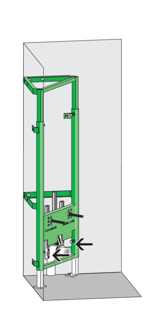
Mounting in a corner (approx. 90°)

-
Position the element at construction height.
The element can be adjusted continuously from 980–1130 mm.
-
Align element.
-
Mark drill holes.

-
Drill holes for the wall fixing and the floor supports.
-
Hit dowel (10 mm) into the wall/floor.
-
Connect water line.

-
Screw the element into the wall and into the floor (size 13 / 17).
-
Clad the element with a single layer of IFGP cladding panels (1 x 12.5 mm).
Mounting in the corner (approx. 90°) with cladding of the drainage line

-
Position the element at construction height.
The element can be adjusted continuously from 980–1130 mm.
-
Remove the floor support where the drainage line is.
-
Align element.
-
Mark drill holes (5 wall fixings and one floor support).

-
Drill holes for the wall fixing and the floor support.
-
Hit dowel (10 mm) into the wall/floor.

-
Connect water line.

-
Screw the element into the wall and into the floor (size 13 / 17).
-
Clad the element with a single layer of IFGP cladding panels (1 x 12.5 mm).
Mounting on the wall (one-sided fixing)

-
Position the element at construction height.
The element can be adjusted continuously from 980–1130 mm.
-
Align element.
-
Mark drill holes (4 wall fixings and two floor supports).

-
Drill holes for the wall fixing and the floor support.
-
Hit dowel (10 mm) into the wall and the floor.

-
Connect water line.

-
Screw the element into the wall and into the floor (size 13).
-
Clad the element with a single layer of IFGP cladding panels (1 x 12.5 mm).
Line mounting of corner elements

- * no scope of delivery
-
Position the elements at construction height.
The element can be adjusted continuously from 980–1130 mm.
-
Align elements.
-
Mark drill holes (each 4 wall fixings and two floor supports).
-
Drill holes for the wall fixing and the floor supports.
-
Hit dowel (10 mm) into the wall and the floor.
-
Connect water line.
-
Screw elements into the wall, into the floor and together (size 13).
-
Clad the corner elements with a single layer of IFGP cladding panels (1 x 12.5 mm).
Mounting in a corner > 90°

-
Position the element at construction height.
The element can be adjusted continuously from 980–1130 mm.
-
Align element.
-
Mark drill holes (4 wall fixings and two floor supports).
-
Drill holes for the wall fixing and the floor support.
-
Hit dowel (10 mm) into the wall and the floor.
-
Connect water line.
-
Screw the element into the wall and into the floor (size 13).
-
Clad the element with a single layer of IFGP cladding panels (1 x 12.5 mm).
Disposal
Separate the product and packaging materials (e. g. paper, metal, plastic or non-ferrous metals) and dispose of in accordance with valid national legal requirements.