Easytop backflow preventer with Rp-thread
Product information
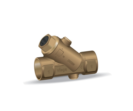
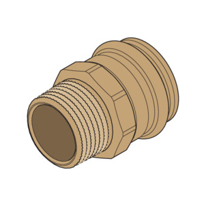
Easytop backflow preventer with Rp-thread
Trade mark rights exist for this document; for further information, go to viega.com/legal .
Target groups
The information in this manual is directed at heating and sanitary professionals and trained personnel.
Individuals without the abovementioned training or qualification are not permitted to mount, install and, if required, maintain this product. This restriction does not extend to possible operating instructions.
The installation of Viega products must take place in accordance with the general rules of engineering and the Viega instructions for use.
Labelling of notes
Warning and advisory texts are set aside from the remainder of the text and are labelled with the relevant pictographs.

DANGER!
This symbol warns of possible life-threatening injury.

WARNING!
This symbol warns of possible serious injury.

CAUTION!
This symbol warns of possible injury.

NOTICE!
This symbol warns of possible damage to property.

INFO!
This symbol gives additional information and hints.
About this translated version
This instruction for use contains important information about the choice of product or system, assembly and commissioning as well as intended use and, if required, maintenance measures. The information about the products, their properties and application technology are based on the current standards in Europe (e.g. EN) and/or in Germany (e.g. DIN/DVGW).
Some passages in the text may refer to technical codes in Europe/Germany. These should serve as recommendations in the absence of corresponding national regulations. The relevant national laws, standards, regulations, directives and other technical provisions take priority over the German/European directives specified in this manual: The information herein is not binding for other countries and regions; as said above, they should be understood as a recommendation.
Standards and regulations
The following standards and regulations apply to Germany / Europe and are provided as a support feature.
Regulations from section: Application areas
Scope / Notice | Regulations applicable in Germany |
|---|---|
Planning, execution, operation and maintenance of potable-water installations | DIN EN 806, part 1 |
Planning, execution, operation and maintenance of potable-water installations | DIN EN 806, part 2 |
Planning, execution, operation and maintenance of potable-water installations | DIN EN 806, part 3 |
Planning, execution, operation and maintenance of potable-water installations | DIN EN 806, part 4 |
Planning, execution, operation and maintenance of potable-water installations | DIN EN 806, part 5 |
Planning, execution, operation and maintenance of potable-water installations | DIN 1988 |
Planning, execution, operation and maintenance of potable-water installations | VDI/DVGW 6023 |
Regulations from section: Media
Scope / Notice | Regulations applicable in Germany |
|---|---|
Suitability for potable water | Trinkwasserverordnung (TrinkwV) |
Regulations from section: Product description
Scope / Notice | Regulations applicable in Germany |
|---|---|
Suitability for potable-water installations | Trinkwasserverordnung (TrinkwV) |
Suitability for potable-water installations | DIN 50930‑6 |
Requirements for plastic components for potable-water installations | DVGW-Arbeitsblatt W270 |
Regulations from section: Overview
Scope / Notice | Regulations applicable in Germany |
|---|---|
Compliance with the inspection requirements (fittings group I) | DIN EN 1213 |
Regulations from section: Threaded connection
Scope / Notice | Regulations applicable in Germany |
|---|---|
Threaded pair | DIN EN 10226‑1 |
Permitted sealants | DIN 30660 |
Permitted sealants | DIN EN 751‑2 |
Regulations from section: Marking on components
Scope / Notice | Regulations applicable in Germany |
|---|---|
Designation noise class I | DIN EN 1213 |
EA marking for classification | DIN EN 1717 |
Regulations from section: Corrosion
Scope / Notice | Regulations applicable in Germany |
|---|---|
External corrosion protection | DIN EN 806‑2 |
External corrosion protection | DIN 1988‑200 |
External corrosion protection | DKI-Informationsdruck i. 160 |
Regulations from section: Establishing threaded connection
Scope / Notice | Regulations applicable in Germany |
|---|---|
Threaded pair | DIN EN 10226‑1 |
Sealant for threaded metal connectors in potable-water installations | DIN 30660 |
Regulations from section: Leakage test
Scope / Notice | Regulations applicable in Germany |
|---|---|
Leakage test of potable-water installations | DIN EN 806, part 4 |
Leakage test of potable-water installations | ZVSHK-Merkblatt |
Regulations from section: Maintenance
Scope / Notice | Regulations applicable in Germany |
|---|---|
Operation and maintenance of potable-water installations | DIN EN 806‑5 |
Intended use
INFO!
Agree the use of the model for areas of application and media other than those described with Viega.
Areas of application
Use is possible in the following areas among others:
potable water installations
Industrial units
Media
The model is also suitable for the following media, amongst others:
Potable water without limitations acc. to the applicable directives, see Regulations from section: Media
Maximum chloride concentration 250 mg/l pursuant to applicable regulations, see Regulations from section: Media
Product description
Overview
INFO!
The Easytop system fittings comply with the test requirements specified in the applicable regulations, see Regulations from section: Overview . Sound protection Lap≤ 20 dB(A)
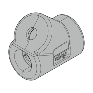
The model is equipped as follows:
Valve casing made of silicon bronze
Valve top made of zero-lead alloy (dead space free)
Dual-sided Rp-thread
Backflow preventer (BP)
- Entleerungs- / Prüfstopfen
Drainage / test plugs G ¼ upstream and downstream of the backflow preventer
Valve and spindle seal made of EPDM (maintenance-free)
Key surface on the casing
Backflow preventer
The model is fitted with a backflow preventer.
Backflow preventers only allow flowthrough in one direction (in the direction of flow). If the direction of flow changes, e.g. due to back suction, the backflow preventers close automatically.
Threaded connection
Prerequisite for a threaded connection, which seals via a thread, is a threaded pair in accordance with applicable regulations, see Regulations from section: Threaded connection . Pursuant to these regulations, a permitted threaded pair comprises a conical external thread and a cylindrical internal thread, e.g. R ¾ and Rp ¾.
Only use commercially available and chloride-free, DVGW approved sealant in accordance with the applicable regulations to seal threads, see Regulations from section: Threaded connection .
Markings on components
The model is marked as follows:
Flow direction indicator
Dimension
DVGW writing
EA marking for classification in accordance with the applicable regulations, see Regulations from section: Marking on components
Compatible components
Please contact the Viega Service Center for questions on this subject.
Operating mode
backflow preventer (BP)
Backflow preventers protect fittings and installation systems against unintended backflow, back pressure or back suction of the contaminated wastewater or dirty water in the piping system. This can occur after pressure fluctuations in the distributor circuit, which can reverse the direction of flow.
The backflow preventer prevents the pushing back, backflow or back suction of liquids, which may be a health hazard, into the public potable water network, with the help of a spring-loaded valve cone. The dimension is dependent on the peak volume flow and it complies with the nominal width of the pipeline. The backflow preventer must be fitted with testing equipment.
In many countries, standards and technical guidelines stipulate the use of backflow preventers or other suitable safety equipment that protect potable water against contamination.
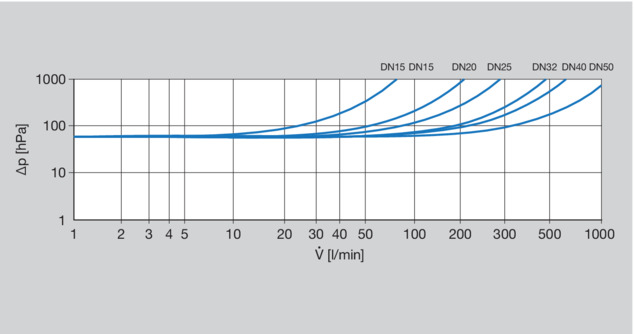
Technical data
Operating temperature [Tmax.] |
|---|
Operating pressure [Pmax] |
90 °C |
1.6 MPa (16 bar) |
The performance diagram shows the pressure losses (in hPa) in relation to the volume flow and the nominal width.
Optional accessories
The following optional accessories are available:
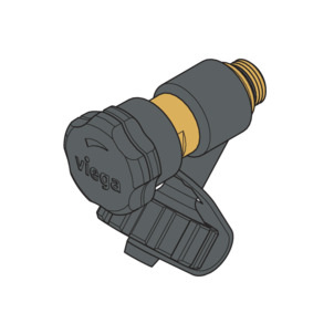
Drainage valve
Extension for drainage valve when using an insulating shell
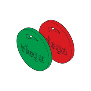
Easytop media markings in the colours red and green for the identification of the corresponding area of use
Insulating shells
Insulating shells
Insulating shells are available for all sizes of valves. The two-piece shells are self-securing and mounted with tools and holding clamps: they connect seamlessly onto the flat surface of the pipe insulation. When installing a drainage valve or an extension with drainage valve, a predetermined breaking point is broken out of the insulating shell.
Handling
Assembly information
Mounting instructions
Checking system components
INFO!
Do not remove the model from the packaging until immediately before use.
System components may, in some cases, become damaged through transportation and storage.
Check all parts.
Contaminated components may not be installed.
During assembly
Observe the following when mounting:
Flow direction indicator
Use suitable tools
Assembly
Establishing the threaded connection
Sealing threaded connections
Only use the following materials for sealing threaded connections:
Sealing hemp and sealing paste
PTFE thread sealing tape
Thread sealing thread
INFO!
Viega R-external thread, knurled on site – no need to roughen before applying hemp.
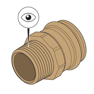
-
Check that the thread is undamaged and in perfect condition.
To prevent the sealant from being pushed out when screwing in, Viega recommends roughening the surface of smooth threads.
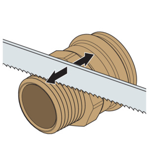
-
Roughen the surface of the thread e.g. with a saw blade.
NOTICE!Be careful not to damage the thread flanks of the thread when roughening.

-
The thread is roughened.
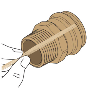
-
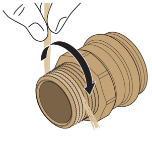
Place some hemp fibres across the thread.

-
Insert the hemp into the thread, starting from the surface to the outside, and always guide it over the hemp lying across.
-
For right-hand threads, wind in a clockwise direction.
-
Insert the hemp into the threaded grooves.
NOTICE!Make sure that there is no hemp on the thread crests. Only in the thread grooves and on the thread flanks does the hemp support the sealing function of the connection.
-
Tie in the crosswise hemp threads on the last two to three turns.
-
For left-hand threads, wind anticlockwise.
-
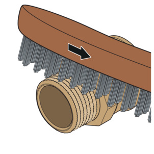
After spooling the last hemp thread, work the hemp in evenly and firmly with a wire brush.
-
The thread is sealed.
Applying thread sealing paste
Sealing paste protects the hemp from drying out and chemical and biological decomposition, facilitates screwing in and fills any cavities remaining in the threads.
For threaded connections, only use non-curing sealants with DVGW or DIN DVGW markings in accordance with applicable guidelines, see Regulations from section: Establishing threaded connection .
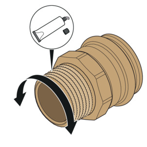
-
Coat the hemp evenly with thread sealing paste.
-
Ensure that the entire hemp/flax is covered with an even layer.
Screwing the threaded connection
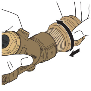
-
Screw the sealed male thread into the backflow preventer by hand.
-
Make sure that no hemp is twisted out or pushed in front of the internal thread.
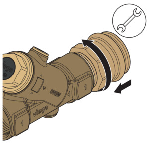
-
Secure the backflow preventer and tighten the threaded connector with a fork spanner.
-
Install the backflow preventer and connector in the piping.
-
Perform a leakage test.
Leakage test
The installer must perform a leakage test before commissioning.
Carry out this test on a system that is finished but not covered yet.
Comply with the general rules of engineering and the applicable directives, see Regulations from section: Leakage test .
Document the result.
Maintenance
NOTICE!
Inform your customer or the operator of the potable water installation that the system has to be maintained on a regular basis.
INFO!
Viega recommends actuating the fitting regularly and checking its function.
Disposal
Separate the product and packaging materials (e. g. paper, metal, plastic or non-ferrous metals) and dispose of in accordance with valid national legal requirements.