Sanfix Fosta
Product information

Sanfix Fosta
Press connector system made of gunmetal/silicon bronze with multi-layer pipes
| Year built (from): | 1.1.2000 |
Trade mark rights exist for this document; for further information, go to viega.com/legal .
Target groups
The information in this manual is directed at heating and sanitary professionals and trained personnel.
Individuals without the abovementioned training or qualification are not permitted to mount, install and, if required, maintain this product. This restriction does not extend to possible operating instructions.
The installation of Viega products must take place in accordance with the general rules of engineering and the Viega instructions for use.
Labelling of notes
Warning and advisory texts are set aside from the remainder of the text and are labelled with the relevant pictographs.

DANGER!
This symbol warns of possible life-threatening injury.

WARNING!
This symbol warns of possible serious injury.

CAUTION!
This symbol warns of possible injury.

NOTICE!
This symbol warns of possible damage to property.

INFO!
This symbol gives additional information and hints.
About this translated version
This instruction for use contains important information about the choice of product or system, assembly and commissioning as well as intended use and, if required, maintenance measures. The information about the products, their properties and application technology are based on the current standards in Europe (e.g. EN) and/or in Germany (e.g. DIN/DVGW).
Some passages in the text may refer to technical codes in Europe/Germany. These should serve as recommendations in the absence of corresponding national regulations. The relevant national laws, standards, regulations, directives and other technical provisions take priority over the German/European directives specified in this manual: The information herein is not binding for other countries and regions; as said above, they should be understood as a recommendation.
Standards and regulations
The following standards and regulations apply to Germany / Europe and are provided as a support feature.
Regulations from section: Fields of application
Scope / Notice | Regulations applicable in Germany |
|---|---|
Planning, execution, operation and maintenance of potable water installations | DIN EN 1717 |
Planning, execution, operation and maintenance of potable water installations | DIN 1988 |
Planning, execution, operation and maintenance of potable water installations | VDI/DVGW 6023 |
Planning, execution, operation and maintenance of potable water installations | Trinkwasserverordnung (TrinkwV) |
Regulations from section: Pipes
Scope / Notice | Regulations applicable in Germany |
|---|---|
Potable water pipelines, cold:
| DIN 1988–200, Table 8 |
Potable water pipelines, warm:
| DIN 1988–200, Table 9 |
Heating systems:
Heating systems in floor construction:
| EnEV, Anhang 5, Table 1 |
Regulations from section: Storage
Scope / Notice | Regulations applicable in Germany |
|---|---|
Requirements for material storage | DIN EN 806‑4, Chapter 4.2 |
Regulations from section: Leakage test
Scope / Notice | Regulations applicable in Germany |
|---|---|
Test on a system that is finished but not yet covered | DIN EN 806–4 |
Leakage test for water installations | ZVSHK-Merkblatt: |
Regulations from section: Maintenance
Scope / Notice | Regulations applicable in Germany |
|---|---|
Operation and maintenance of potable water installations | DIN EN 806‑5 |
Intended use
INFO!
Coordinate the use of the system for areas of use and media other than those described with the Viega Service Center.
Areas of use
Use is possible in the following areas among others:
Sanfix Fosta multi-layer pipe (dimensionally stable with oxygen barrier layer)
Potable water installations
Heating systems
Compressed air systems
Potable water installation
For planning, execution, operation and maintenance of potable water installations, observe the applicable regulations, see Regulations from section: Fields of application .
Maintenance
Inform your customer or the operator of the potable water installation that the system has to be maintained on a regular basis, see Regulations from section: Fields of application .
Media
The system is suitable for the following media, amongst others:
Sanfix Fosta multi-layer pipes
Potable water
Rainwater
Heating water
Compressed air
Operating conditions
Operating temperature max.
Sanitary installations: TD 70 °C
Heating installations: 80 °C
Operating pressure max.
Sanitary installations: 1.0 MPa (10 bar)
Heating installations: 1.0 MPa (10 bar)
Product description
Overview
The piping system consists of press connectors in connection with multi-layer pipes and the corresponding press tools.
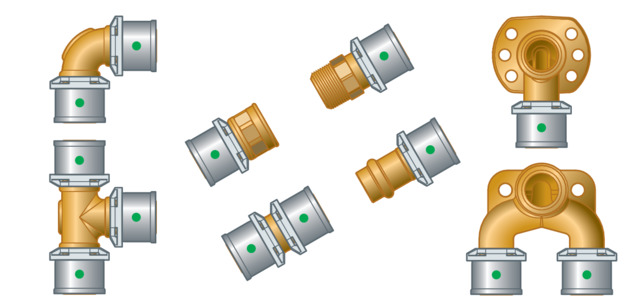
The system components are available in the following dimensions: d 16 / 20 / 25 / 32 / 40 / 50 / 63.
Pipes
Sanfix Fosta plastic pipes are available in coiled bundles with and without protective pipe and with various insulation thicknesses. Dimensionally stable and flexible multi-layer pipes are also available in 5 m lengths. The following pipes are available from the system described:
Sanfix Fosta multi-layer pipe |
|---|
Dimensionally stable |
With oxygen barrier layer |
d 16, 20, 25, 32, 40, 50, 63 |
Sanfix Fosta multi-layer pipe
Type of pipe |
|---|
Pipe in lengths |
Pipe without protective pipe |
Pipe with protective pipe (black) |
Pipe with 6 mm surrounding insulation (grey) |
Pipe with 9 mm surrounding insulation (grey) |
Pipe with eccentric heat insulation (grey) |
d | Areas of use |
|---|---|
16, 20, 25, 32, 40, 50, 63 | Potable water and heating installations |
16, 20, 25 | Potable water and heating installations |
16, 20 | Potable water and heating installations1) |
16, 20 | Potable water and heating installations |
16, 20, 25 | Potable water and heating installations1) |
16, 20 | Heating pipes in floor construction, integration in the floor construction without continuous footfall sound insulation1) |
1)
| see Regulations from section: Pipes |
Laying and fixing pipes
Only pipe clamps with chloride-free sound insulating inlays should be used to secure the pipes.
For fastening the pipes on Prevista Dry Plus rail systems, Viega recommends the use of the Prevista Dry Plus piping support (model 8416). The piping support is suitable for plastic pipelines with dimensions d16 to 20.
Observe the general rules of fixing technology:
Do not use fixed pipelines as a support for other pipelines and components.
Do not use pipe hooks.
Observe distance to press connectors.
Observe the expansion direction: Plan fixed and gliding points.
Make sure to affix the pipelines in such a way as to de-couple them from the installation body, so that they cannot transfer any structure-borne sound, resulting from thermal expansion or possible pressure surges, onto the installation body or other components.
Observe the following fixing intervals:
Interval between the pipe clamps
d x s [mm] |
|---|
16 x 2.2 |
20 x 2.8 |
25 x 2.7 |
32 x 3.2 |
40 x 3.5 |
50 x 4.0 |
63 x 4.5 |
Horizontal Sanfix Fosta multi-layer pipes [m] | Vertical Sanfix Fosta multi-layer pipes [m] |
|---|---|
1.00 | 1.30 |
1.00 | 1.30 |
1.50 | 1.95 |
2.00 | 2.60 |
2.00 | 2.60 |
2.50 | 3.25 |
2.50 | 3.25 |
Length expansion
Pipelines expand with heat. Heat expansion is dependent on the material. Changes in length lead to tension within the installation. These tensions must be equalised with suitable measures.
The following are effective:
Fixed and gliding points
Expansion equalisation joints (expansion bends)
Heat expansion co-efficients of various pipe materials
Material | Heat expansion co-efficient ⍺ | Example: Length expansion with pipe lengths L = 20 m and ΔT = 50 K |
|---|---|---|
Sanfix Fosta multi-layer pipe | 0.03 | 30 |
Length expansion and expansion bend length
Calculation example Sanfix Fosta multi-layer pipe:
Given: Temperature difference Δ ϑ = 50 K; Pipe length L = 8 m; Pipe ⌀ = 20 mm
Required: Expansion bend lengthLBS
Calculation:
Beginning in the left-hand diagram: From 50 K temperature difference on the x-axis up to the characteristic line for the 8 m pipe length.
Connect the intersection horizontally with the right-hand diagram up to the intersection of the characteristic line for pipe diameter 20 mm.
Result: Read the value from the x-axis:LBS = 480 mm.
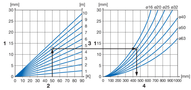
- 1 - Length expansion ∆l [mm]
- 2 - Temperature difference ∆ϑ [K]
- 3 - Pipe length L [m]
- 4 - Expansion bend length LBS [mm]
Press connectors

SC‑Contur
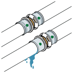
Viega press connectors are equipped with the SC‑Contur. The SC‑Contur is a safety technology that is certified by the DVGW and ensures that the press connector is guaranteed to be leaky in an unpressed state. In this way, inadvertently unpressed connections are noticed during a leakage test.
Viega guarantees that accidentally unpressed connections become visible during a leakage test:
with the wet leakage test in the pressure range from 0.1–0.65 MPa (1.0–6.5 bar)
with dry leakage test in the pressure range from 22 hPa–0.3 MPa (22 mbar–3.0 bar)
Sealing elements
The press connectors are factory-fitted with EPDM sealing elements.
Markings on components
Pipe marking
The pipe markings contain important information regarding the quality and certification of the pipes. Their meaning is as follows:
manufacturer
system name
pipe material
size / wall thickness
certification and operating temperatures
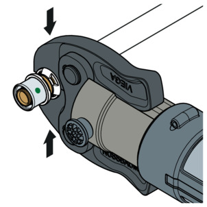
Markings on press connectors
The green dot shows that the press connector is equipped with the SC‑Contur and that the system is suitable for potable water.
Mixed installations
All Sanfix Fosta pipes may be mounted only using original accessories, Sanfix connectors using SC‑Contur and the corresponding press tools. Use with components of other plastic piping systems, such as Raxofix, for example, is not permitted.
Please contact the Viega Service Center if you have any questions on this subject.
Handling
Storage
For storage, comply with the requirements specified in the applicable regulations, see Regulations from section: Storage :
Store rods on even, clean surfaces.
Storage outside in closed, original packaging is possible for a period of up to three months. In this instance, protect the packaging from damage due to rain or high levels of humidity or UV radiation.
Assembly information
Mounting instructions
Checking system components
System components may, in some cases, become damaged through transportation and storage.
Check all parts.
Replace damaged components.
Do not repair damaged components.
Contaminated components may not be installed.
Permitted exchange of sealing elements
If the sealing element in the press connector is obviously damaged, it should be exchanged for a Viega spare sealing element made of the same material.
Space requirements and intervals
Pressing between pipelines
Space requirement type 2 (PT2), PT3-EH, PT3-AH, Pressgun 4B, 4E, 5
d |
|---|
a [mm] |
b [mm] |
16 | 20 | 25 | 32 | 40 | 50 | 63 |
|---|---|---|---|---|---|---|
15 | 16 | 23 | 21 | 28 | 40 | 56 |
45 | 45 | 58 | 65 | 70 | 85 | 125 |
Space requirement Picco, Pressgun Picco
d |
|---|
a [mm] |
b [mm] |
16 | 20 | 25 | 32 |
|---|---|---|---|
15 | 15 | 20 | 25 |
48 | 50 | 55 | 70 |
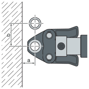
Pressing between pipe and wall
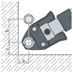
Space requirement type 2 (PT2), PT3-EH, PT3-AH, Pressgun 4B, 4E, 5
d |
|---|
a [mm] |
b [mm] |
c [mm] |
16 | 20 | 25 | 32 | 40 | 50 | 63 |
|---|---|---|---|---|---|---|
20 | 20 | 25 | 30 | 35 | 40 | 54 |
76 | 76 | 80 | 90 | 92 | 95 | 140 |
25 | 25 | 35 | 35 | 43 | 55 | 61 |
Space requirement Picco, Pressgun Picco
d |
|---|
a [mm] |
b [mm] |
c [mm] |
16 | 20 | 25 | 32 |
|---|---|---|---|
20 | 21 | 25 | 30 |
70 | 74 | 75 | 80 |
28 | 28 | 35 | 40 |
Pressing in wall slots

Space requirement type 2 (PT2), PT3-EH, PT3-AH, Pressgun 4B, 4E, 5
d |
|---|
a [mm] |
b [mm] |
c [mm] |
16 | 20 | 25 | 32 | 40 | 50 | 63 |
|---|---|---|---|---|---|---|
20 | 20 | 25 | 30 | 35 | 40 | 54 |
90 | 90 | 90 | 95 | 92 | 95 | 140 |
140 | 140 | 140 | 155 | 178 | 205 | 262 |
Space requirement Picco, Pressgun Picco
d |
|---|
a [mm] |
b [mm] |
c [mm] |
16 | 20 | 25 | 32 |
|---|---|---|---|
20 | 21 | 25 | 30 |
80 | 80 | 80 | 80 |
120 | 120 | 120 | 160 |
Z dimensions
For the Z dimensions, refer to the respective product page in the online catalogue.
Required tools
The use of original Viega tools or equivalent tools is recommended for installation.
The following tools are required for production of a press connection:
INFO!
Hand or electric saws or angle grinders are not permitted.
press machine with constant pressing force
Suitable for Sanfix press jaws (model 2299.7 or 2484.7)
pipe shear (model 5341) for dimensions 16–25 mm
pipe cutters (model 2191) for dimensions 32–63 mm
bending tool (model 5331 or 5331.2)
calibrating tool suitable for the pipe size:
16 / 20 mm (model 2139.0)
25 / 32 / 40 mm (model 2139.3)
50 / 63 mm (model 2139.2)
INFO!
Viega recommends the use of Viega system tools when installing the press fittings.
The Viega system press tools have been developed and tailored specifically for the installation of Viega press connector systems.
Assembly
Replacing the sealing element
Removing the sealing element
INFO!
Do not use pointed or sharp-edged objects to remove the sealing element. They may damage the sealing element.
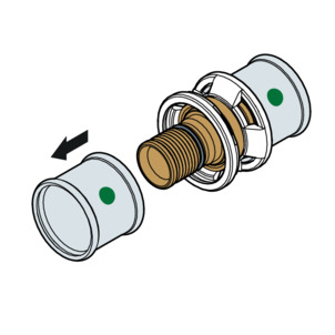
-
Remove the press sleeve.
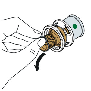
-
Remove the sealing element from the recess.
Inserting the sealing element
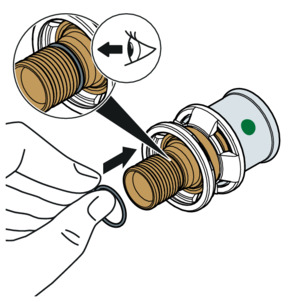
-
Insert a new, undamaged sealing element into the recess.
-
Check if the whole sealing element is in the recess.

-
Insert the press sleeve.
Bending pipes
Sanfix multi-layer pipes in the dimensions 16–32 mm can be bent by hand with a bending radius of 5 x d or with a bending tool with the following radii:
d | Bending radius x d |
|---|---|
16 | 2.0 |
20 | 2.3 |
25 | 3.0 |
32 | 3.5 |
40 | 4.0 |
50 | 4.5 |
63 | 4.5 |
The recommended bending tools for dimensions d 16 and 20 are the models 5331 and 5331.2.
Shortening the pipes
For information about tools, also see Required tools .
Dimensions 16–25 mm
-
Cut the protective pipe to length using the protective pipe cutter (model 5341).

-
Cut the pipe to length using a pipe shear.
Replace worn blades (model 5341.6).
Make sure that the cut surface is clean and straight.
Dimensions 32–63 mm
-
Cut the pipe to length using a pipe cutter (model 2191).
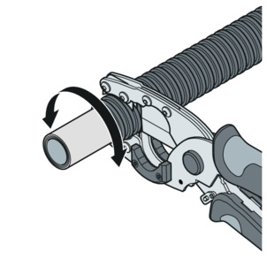
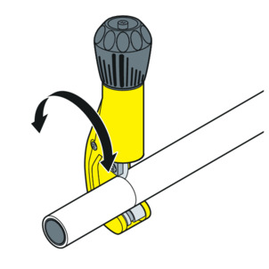
Calibrating the pipes
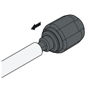
-
Using the calibration device, prepare pipe ends ≥ 25 mm and deformed pipe ends before pressing.
Push the calibration device in as far as it will go.

-
Calibrate the pipe with turning movements.
-
The pipe is calibrated.
Pressing the connection

-
Push the pipe into the press connector until the pipe end is visible in the inspection window.
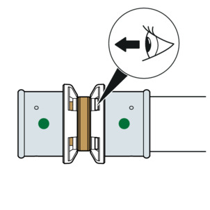
-
Check the insertion depth in the inspection window.
-
Open the press jaw and place it at a right-angle onto the press connector.
Observe the intervals in section Space requirements and intervals .
-
Carry out the pressing process.
-
Connection is pressed.
Leakage test
The installer must perform a leakage test before commissioning.
Carry out this test on a system that is finished but not covered yet.
Observe the applicable regulations, see Regulations from section: Leakage test .
The leakage test pursuant to the applicable regulations must also be carried out for non-potable water installations, see Regulations from section: Leakage test .
Document the result.
Maintenance
Observe the applicable regulations for the operation and maintenance of potable water installations, see Regulations from section: Maintenance .
Disposal
Separate the product and packaging materials (e. g. paper, metal, plastic or non-ferrous metals) and dispose of in accordance with valid national legal requirements.